Cart
0
Product
Products
(empty)
No products
$0.00
Total
Product successfully added to your shopping cart
Quantity
Total
There are 0 items in your cart.
There is 1 item in your cart.
Total products
Total
 View larger
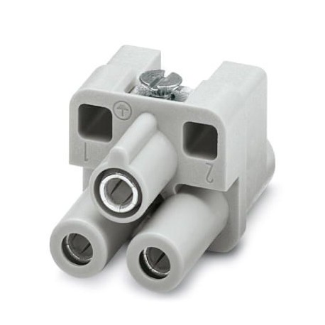
HC-HS 2-D7-EBUS 1586264 PHOENIX CONTACT Contact insert
HC-HS 2-D7-EBUS
1586264
PHOENIX_CONTACT
10
Contact insert
Connectors > Contact insert for rectangular connectors
Industrial plug-in connectors/interfaces
* Brand new product in its original packaging covered by the warranties and certifications provided by PHOENIX_CONTACT
More info
▲Key Commercial Data
| Orderkey | 1586264 |
|---|---|
| Packing unit | 10 pc |
| Minimum order quantity | 10 pc |
| Note | Made to Order (non-returnable) |
| Catalog page | Page 507 (C-2-2017) |
| GTIN | 4046356410212 |
| Weight per Piece (excluding packing) | 18.660 g |
| Custom tariff number | 85366990 |
| Country of origin | DE (Germany) |
General
| Note | for HC-D7 housing, axial connection 2.0 mm, Allen key |
|---|---|
| The axial screw connection must be established using a 2 mm Allen key (for stranded conductors only) | |
| Connection method | Axial screw connection |
| Tightening torque | 1.8 Nm |
| Degree of pollution | 3 |
| Overvoltage category | III |
| Number of positions | 2+PE |
| Insertion/withdrawal cycles | ≥ 500 |
| Size | D7 |
| Contact numbering | 1 - 2 |
| Conductor cross section | 4 mm² ... 10 mm² |
| Connection cross section AWG | 10 ... 8 |
| Stripping length of the individual wire | 8 mm +1 |
| Assembly instructions | To ensure correct use, installation in housing with IP54 protection or better is required |
| Connection | Note regarding axial connection technology: Only for stranded wires. The specified conductor cross sections refer to the geometric cross section of the cable used. Cables with a geometric cross section which deviates significantly from the nominal cable cross section must be checked before use. The axial connection technology connection space is designed for fine strand cables according to VDE 0295 Class 5. Deviating cable structures (e.g., Class 6 cables) must be checked before use. Assembly instructions Before assembly, ensure that the tapered screw is fully loosened (chamber is open). Cables must not be twisted. The wires must be pushed into the contact chamber as far as they will go (until the insulation touches the contact). Hold the wires in position and tighten using an Allen key. The used wire end must be cut off before reconnection. The terminal screw must only be retightened once to prevent the litz wires from breaking. To prevent damage to the contact, the wire/cable must be mechanically held at an appropriate distance from the connection point (e.g., when used in a plate cut out). For notes on correct execution, see DIN VDE 0100-520:2003-06. Unused connections must be tightened with maximum torque. |
Ambient conditions
| Ambient temperature (operation) | -40 °C ... 125 °C (including heating up of contacts) |
|---|
Standards and Regulations
| Connection in acc. with standard | CUL |
|---|---|
| Constructional and testing regulations | DIN VDE 0627/86 |
| DIN VDE 0110/02.79 | |
| DIN VDE 0110-1/04.97 | |
| IEC 60664-1, DIN IEC 60512 | |
| IEC 60352 | |
| Flammability rating according to UL 94 | V0 |
Environmental Product Compliance
| REACh SVHC | Lead 7439-92-1 |
|---|---|
| China RoHS | Environmentally Friendly Use Period = 50 |
| For details about hazardous substances go to tab “Downloads”, Category “Manufacturer's declaration” |
Classifications
eCl@ss 4.0272607xxeCl@ss 4.127260701eCl@ss 5.027143424eCl@ss 5.127261200eCl@ss 6.027261200eCl@ss 7.027440205eCl@ss 8.027440205eCl@ss 9.027440205
Datasheet - PDF
▲| Title: | Size: | Type: |
|---|---|---|
| PDF CATALOG PHOENIX CONNECTORS EN.pdf | 57 Mbytes |

|
| PHOENIX CONTACT-1586264-HC-HS 2-D7-EBUS | 130 Kbytes |
 |
Reviews (0) ▲
No customer reviews for the moment.
Add Review
hide form
| Rating: |


|
| Name: | |
| Email: | |
| Subject: | |
| Text: | |
| Do you recommend this product to buy? | |
|
|
|
| Add review | |
All ratings we receive from the items we offer are real and verified. A small gesture, but a lot of value. That's why we thank you for that minute you invest in leaving us your opinion and qualification about the products, because it helps us to continue improving and to offer you a service of even higher quality.


