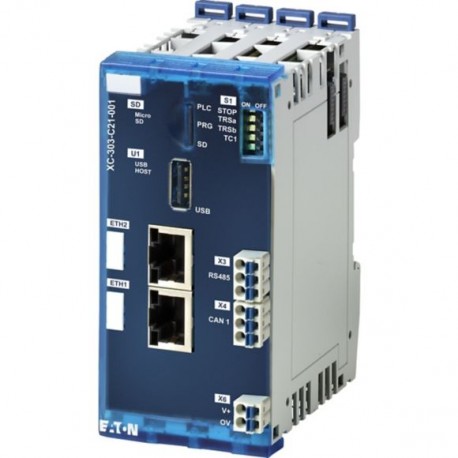
XC-303-C21-001 191081 EATON ELECTRIC PLC XC300 Modular Programable con CODESYS V3 Slot SD USB 2 x Ethernet 2.. Ver más grande
Las imágenes son sólo a título ilustrativo. Por favor, revise la ficha técnica.

XC-303-C21-001 191081 EATON ELECTRIC PLC XC300 Modular Programable con CODESYS V3 Slot SD USB 2 x Ethernet 2..

XC-303-C21-001

191081

EATON-MOELLER

PLC XC300 Modular; Programable con CODESYS V3; Slot SD; USB; 2 x Ethernet; 2 x CAN; RS485

PLC XC300 Modular Programable con CODESYS V3 Slot SD USB 2 x

Eaton XC XC303 modular PLC, small PLC, programmable CODESYS 3, SD Slot, USB, 2x Ethernet, CAN, RS485

Más detalles


Controladores industriales (PLC) > Unidad base de PLC

Módulos E/S Remotas XN300

* Producto nuevo en su embalaje original con todas las garantías y certificaciones de EATON-MOELLER

Precio total: $877.65
Precio unitario: $877.65

*Este precio es por unidad y muestra el valor neto (no incluye impuestos indirectos si son aplicables).

Si nuestro precio no es el mejor solicítenos presupuesto Solicitar presupuesto

Más vendidos

Más Información


Especificaciones generales

Product Name
Eaton XC Modular PLC
Catalog Number
191081
EAN
4015081915675
Product Length/Depth
108 mm
Product Height
65 mm
Product Width
85 mm
Product Weight
0.28 kg
Certifications
CE
EN 61131
UL listed
EAC
UL File No.: E205091
cULus Listed
Catalog Notes
Protective devices must be installed directly at the inductive load in order to prevent interference.
Model Code
XC-303-C21-001

Features & Functions

Features
Short-circuit protection (digital outputs)
Functions
Redundancy
Additional program memory possible

General

Connection type
Push-in spring-cage terminal, Connection design in TOP direction
Degree of protection
IP20
Memory capacity
512,000 kByte
Model
Modular
Mounting method
Rail mounting possible
Overvoltage category
II
Pollution degree
2
Protocol
MODBUS
Other bus systems
CAN
TCP/IP
EtherNet/IP
Rated operational voltage
24 V
160 V (terminations)
Voltage type
DC

Ambient conditions, mechanical

Height of fall (IEC/EN 60068-2-32) - max
1 m
Mounting position
Vertical (on horizontal top-hat rail)
Shock resistance
15 g, Mechanical, according to IEC/EN 60068-2-27, Half-sinusoidal shock 11 ms, 9 Impacts
Vibration resistance
5 - 8.4 / 8.4 -150 Hz, 3,5 mm / 1 g

Climatic environmental conditions

Air pressure
795 - 1080 hPa (operation)
Ambient operating temperature - min
-20 °C
Ambient operating temperature - max
55 °C
Ambient storage temperature - min
-40 °C
Ambient storage temperature - max
80 °C
Climatic proofing
Damp heat, constant, to IEC 60068-2-3
Dry heat to IEC 60068-2-2
Environmental conditions
Condensation: prevent with appropriate measures
Relative humidity
< 95 % (non-condensing)

Electro magnetic compatibility

Air discharge
8 kV/4 kV, Air/contact discharge, ESD
Burst impulse
2 kV, Supply cable
1 kV, Signal cable
Electromagnetic fields
10 V/m at 0.08 - 1.0 GHz (according to IEC EN 61000-4-3)
1 V/m at 2 - 2.7 GHz (according to IEC EN 61000-4-3)
3 V/m at 1.4 - 2 GHz (according to IEC EN 61000-4-3)
Emitted interference
47 dB (at 230 - 1000 MHz, Class A, radiated, high frequency)
40 dB (at 30 - 230 MHz, Class A, radiated, high frequency)
Radiated RFI
10 V
Surge rating
0.5/0.5 kV, Supply cable, balanced/unbalanced), EMC
1 kV, Signal cable, unbalanced, EMC

Terminal capacities

Terminal capacity (AWG)
24 - 16
Terminal capacity (flexible with ferrule)
0.25 - 1.5 mm², with ferrules without plastic collar according to DIN 46228-1 (ferrules crimped gas-tight)
0.25 - 1.5 mm², with ferrules with plastic collar according to DIN 46228-1 (ferrules crimped gas-tight)
Terminal capacity (flexible)
0.2 - 1.5 mm², H 07V-K
Terminal capacity (solid)
0.2 - 1.5 mm², H07V-U
Stripping length (main cable)
10 mm
Gauge pin
A1 (according to IEC/EN 60947-1)
Insulating material group
I

Power supply

Heat dissipation
0.1 W (Digital outputs, internal, per active channel)
0.05 W (Digital inputs according to EN61131-2 Type 1, per active channel)
Input voltage
15 - 30 V (Digital inputs, high level)
24 V DC (Digital inputs)
0 - 5 V (Digital inputs, low level)
Supply voltage at AC, 50 Hz - max
0 VAC
Output current
0.5 A
Supply voltage at DC - max
30 VDC
Supply voltage at AC, 50 Hz - min
0 VAC
Supply voltage at DC - min
18 VDC
Voltage dips
Voltage dips: 10 ms/Voltage fluctuations: Yes

Input/Output

Delay time
200 µs, Digital outputs, Delay on signal change and resistive load, from High to Low signal
200 µs, Digital outputs, Delay on signal change and resistive load, from Low to High signal
Digital outputs
Note: Protective devices must be installed directly at the inductive load in order to prevent interference.
Input current
≤ 1.1 mA (Digital inputs, low level)
≥ 2.3 mA (Digital inputs, high level)
2 mA (Ie)
Input delay
300 µs (rising edge)
300 µs (falling edge)
Load current
Max. 6 A per 1.5 mm² (cross-sectional area)
Number of channels
4, Digital Outputs
Number of inputs (analog)
0
Number of inputs (digital)
0
Number of outputs (analog)
0
Number of outputs (digital)
0
Number of relay outputs
0
Rated operational current (Ie)
2.8 A (supply input)
Utilization factor
100 % (Ʃ IAmax = 2A)

Safety

Explosion safety category for dust
None
Explosion safety category for gas
None
Potential isolation
Between Digital inputs: no
Between Digital outputs: no

Design verification

Static heat dissipation, non-current-dependent Pvs
8 W
Heat dissipation details
The max. heat dissipation is specified as the maximum power produced inside the device's housing.
10.2.2 Corrosion resistance
Meets the product standard's requirements.
10.2.3.1 Verification of thermal stability of enclosures
Meets the product standard's requirements.
10.2.3.2 Verification of resistance of insulating materials to normal heat
Meets the product standard's requirements.
10.2.3.3 Resist. of insul. mat. to abnormal heat/fire by internal elect. effects
Meets the product standard's requirements.
10.2.4 Resistance to ultra-violet (UV) radiation
Meets the product standard's requirements.
10.2.5 Lifting
Does not apply, since the entire switchgear needs to be evaluated.
10.2.6 Mechanical impact
Does not apply, since the entire switchgear needs to be evaluated.
10.2.7 Inscriptions
Meets the product standard's requirements.
10.3 Degree of protection of assemblies
Meets the product standard's requirements.
10.4 Clearances and creepage distances
Meets the product standard's requirements.
10.5 Protection against electric shock
Does not apply, since the entire switchgear needs to be evaluated.
10.6 Incorporation of switching devices and components
Does not apply, since the entire switchgear needs to be evaluated.
10.7 Internal electrical circuits and connections
Is the panel builder's responsibility.
10.8 Connections for external conductors
Is the panel builder's responsibility.
10.9.2 Power-frequency electric strength
Is the panel builder's responsibility.
10.9.3 Impulse withstand voltage
Is the panel builder's responsibility.
10.9.4 Testing of enclosures made of insulating material
Is the panel builder's responsibility.
10.10 Temperature rise
The panel builder is responsible for the temperature rise calculation. Eaton will provide heat dissipation data for the devices.
10.11 Short-circuit rating
Is the panel builder's responsibility.
10.12 Electromagnetic compatibility
Is the panel builder's responsibility.
10.13 Mechanical function
The device meets the requirements, provided the information in the instruction leaflet (IL) is observed.

Datasheet - PDF

Opiniones: (0)

Ningún comentario por el momento.

Añadir comentario
ocultar
Valoración:
Nombre:
Email:
Título:
Opinión:
  Captcha
  Añadir comentario

Todas las valoraciones que recibimos de los artículos que ofrecemos son reales y están verificadas. Un pequeño gesto, pero de mucho valor. Por eso, te agradecemos ese minuto que inviertes en dejarnos tu opinión y calificación sobre los productos, porque nos ayuda a seguir mejorando y a ofrecerte un servicio de todavía mayor calidad.