
No products
Product successfully added to your shopping cart


 View larger

F3S-TGR-SPSA-M1J8 387929 AA040390R OMRON Switch Sec. PLe Independ. Plast. 1 sensor 2NC+1NO LED M12-8p
F3S-TGR-SPSA-M1J8
387929
AA040390R
OMRON
Switch Sec. PLe Independ. Plast. 1 sensor 2NC+1NO LED M12-8p
Switch Sec. PLe Independ. Plast. 1 x 2NC+1NA LED M12-8p sensor
Safety > Contactless Switches TGR
Brand new product in its original packaging covered by the warranties and certifications provided by OMRON
Best sellers
▲More info
▲Standalone non-contact door switch
Standalone non-contact switches support applications like guarding doors or position monitoring in machines. They are using the proven Omron non-contact technology allowing to cover mechanical tolerances and vibrations.
- Models with single or dual actuator available
- Based on hall technology
- Connect up to 20 switches in series
- LED for easy diagnosis
- Operates behind stainless steel fittings
- Non-contact – no abrasion – no particles
- Compensation of mechanical tolerances
- Suitable for high pressure cleaning, CIP and SIP processes due IP69K (pre-wired types)
- Conforms to safety categories up to PLe acc. EN ISO 13849-1
Switches
Polyester housing
 | ||
 | ||
Stainless steel housing
 | ||
 | ||
Accessories
Set of Torx safety screws (M4, 4 × 30 mm, 4 × 20 mm, 4 × 10 mm; incl. washers and Torx bit) | ||
Specifications
Mechanical data
Green LED: Indication of safety circuits closed (Guard closed, actuator present, feedback circuit checked) | |||
Yellow LED: Indication of safety circuits open (Actuator removed) | |||
Electrical data
Approved standards
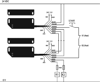
Wiring example (serial connection with manual restart)
Datasheet - PDF
▲| Title: | Size: | Type: |
|---|---|---|
| PDF CATALOGO OMRON AUTOMATION EN.pdf | 19 Mbytes |

|
| PDF CATALOG OMRON 2024 EN.pdf | 25 Mbytes |
|
| F3S-TGR-SPSA-M1J8 AA040390R 387929 f15e_f3s_tgr_s_a_d_standalone_non_contact_safety_switches_datasheet_en.pdf | 2 Mbytes |
|
Reviews (0) ▲
No customer reviews for the moment.
| Rating: |
|
| Name: | |
| Email: | |
| Subject: | |
| Text: | |
| Do you recommend this product to buy? | |
|
|
|
| Add review | |
All ratings we receive from the items we offer are real and verified. A small gesture, but a lot of value. That's why we thank you for that minute you invest in leaving us your opinion and qualification about the products, because it helps us to continue improving and to offer you a service of even higher quality.