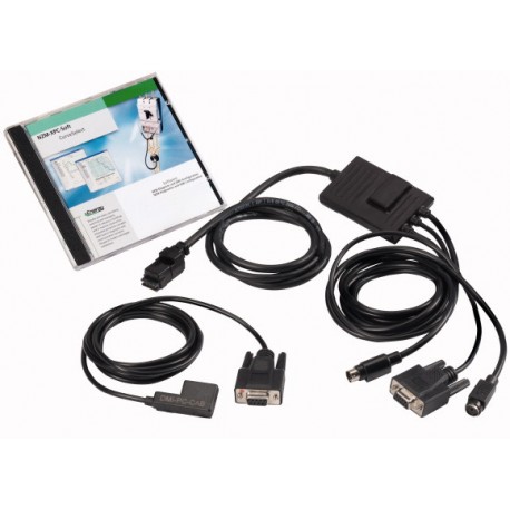
NZM-XPC-KIT 265631 0004359056 EATON ELECTRIC 265631 NZM-XPC-KIT View larger
Images are for illustrative purposes only. Please refer to data sheet for details.

NZM-XPC-KIT 265631 0004359056 EATON ELECTRIC 265631 NZM-XPC-KIT

NZM-XPC-KIT

265631

0004359056

EATON-MOELLER

Software kit, for NZM and DMI

More details


Circuit Breakers NZM Accessories

* Brand new product in its original packaging covered by the warranties and certifications provided by EATON-MOELLER

* This article may be obsolete. Ask for a quotation and we will check if there are any units available. If not, one of our technicians will look for an alternative solution.

If our price is not the best, please ask us for a quote. Ask for a quotation

More info


Software kit, for NZM and DMI
EL-Nummer (Norway)
0004359056
Optional accessories for circuit-breaker series NZM offers a comprehensive portfolio of application possibilities for worldwide use. Modular functional groups make mounting flexible and simple. Note: PC software for direct connection to all new NZM circuit-breakers with electronic releases (IEC and UL/CSA devices) or on the DMI module, including connection cable for NZM. Online display protection parameters and characteristic-curve representations, export possibility to Moeller CurveSelect characteristic-curves program. Warning and release messages: Reading of diagnostic memory also in volt-free status. load currents, display and trend indication. Recording and export options to Excel for load currents and diagnostic messages. Configuration of the DMI motor starter, remote operator configuration of DMI inputs and outputs., display indicators. Only for use in combination with circuit-breakers having electronic releases. Order connecting cable to DMI separately: EASY-USB-CAB. Usable for NZM2(-4), NZM3(-4), NZM4(-4)
[

Delivery program

Accessories
Diagnostics, communication
Description
Diagnostics and configuration software for NZM and DMI (local)
PC software for direct connection to all NZM circuit-breakers with electronic releases (IEC and UL/CSA devices), including the connection cable required in order to connect to an NZM device.
• Protection parameter: Online display and curve display, export option to curve characteristics program “Moeller CurveSelect”.
• Warning and release messages: Reading of diagnostic memory also in volt-free state.
• Load currents: Display and trend indication.
• Recording and export options to Excel for load currents and diagnostic messages.
• Configuration of the DMI: Motor starter, remote operator, assignment of the DMI inputs and outputs and displays.
For use with
NZM2(-4)
NZM3(-4)
NZM4(-4)
Notes

Download the manual AWB1230-1459 and demo-software at www.moeller.net.

Order connecting cable to DMI separately: EASY-USB-CAB.

Notes

Only in combination with circuit-breakers withelectronictrip blocks.

,

Design verification as per IEC/EN 61439

IEC/EN 61439 design verification
10.2 Strength of materials and parts10.2.2 Corrosion resistance
Meets the product standard's requirements.
10.2 Strength of materials and parts10.2.3.1 Verification of thermal stability of enclosures
Meets the product standard's requirements.
10.2 Strength of materials and parts10.2.3.2 Verification of resistance of insulating materials to normal heat
Meets the product standard's requirements.
10.2 Strength of materials and parts10.2.3.3 Verification of resistance of insulating materials to abnormal heat and fire due to internal electric effects
Meets the product standard's requirements.
10.2 Strength of materials and parts10.2.4 Resistance to ultra-violet (UV) radiation
Meets the product standard's requirements.
10.2 Strength of materials and parts10.2.5 Lifting
Does not apply, since the entire switchgear needs to be evaluated.
10.2 Strength of materials and parts10.2.6 Mechanical impact
Does not apply, since the entire switchgear needs to be evaluated.
10.2 Strength of materials and parts10.2.7 Inscriptions
Meets the product standard's requirements.
10.3 Degree of protection of ASSEMBLIES
Does not apply, since the entire switchgear needs to be evaluated.
10.4 Clearances and creepage distances
Meets the product standard's requirements.
10.5 Protection against electric shock
Does not apply, since the entire switchgear needs to be evaluated.
10.6 Incorporation of switching devices and components
Does not apply, since the entire switchgear needs to be evaluated.
10.7 Internal electrical circuits and connections
Is the panel builder's responsibility.
10.8 Connections for external conductors
Is the panel builder's responsibility.
10.9 Insulation properties10.9.2 Power-frequency electric strength
Is the panel builder's responsibility.
10.9 Insulation properties10.9.3 Impulse withstand voltage
Is the panel builder's responsibility.
10.9 Insulation properties10.9.4 Testing of enclosures made of insulating material
Is the panel builder's responsibility.
10.10 Temperature rise
The panel builder is responsible for the temperature rise calculation. Eaton will provide heat dissipation data for the devices.
10.11 Short-circuit rating
Is the panel builder's responsibility. The specifications for the switchgear must be observed.
10.12 Electromagnetic compatibility
Is the panel builder's responsibility. The specifications for the switchgear must be observed.
10.13 Mechanical function
The device meets the requirements, provided the information in the instruction leaflet (IL) is observed.
,

Technical data ETIM 7.0

PLC's (EG000024) / Fieldbus, decentr. periphery - communication module (EC001604)
Electric engineering, automation, process control engineering / Control / Field bus, decentralized peripheral / Field bus, decentralized peripheral - communications module ([email protected] [BAA073013])
Supply voltage AC 50 Hz
0 - 0 V
Supply voltage AC 60 Hz
0 - 0 V
Supply voltage DC
0 - 0 V
Voltage type of supply voltage
DC
Voltage type of supply voltage
DC
Supporting protocol for TCP/IP
No
Supporting protocol for PROFIBUS
No
Supporting protocol for CAN
No
Supporting protocol for INTERBUS
No
Supporting protocol for ASI
No
Supporting protocol for KNX
No
Supporting protocol for MODBUS
No
Supporting protocol for Data-Highway
No
Supporting protocol for DeviceNet
No
Supporting protocol for SUCONET
No
Supporting protocol for LON
No
Supporting protocol for SERCOS
No
Supporting protocol for PROFINET IO
No
Supporting protocol for PROFINET CBA
No
Supporting protocol for Foundation Fieldbus
No
Supporting protocol for EtherNet/IP
No
Supporting protocol for AS-Interface Safety at Work
No
Supporting protocol for DeviceNet Safety
No
Supporting protocol for INTERBUS-Safety
No
Supporting protocol for PROFIsafe
No
Supporting protocol for SafetyBUS p
No
Supporting protocol for other bus systems
No
Radio standard Bluetooth
No
Radio standard WLAN 802.11
No
Radio standard GPRS
No
Radio standard GSM
No
Radio standard UMTS
No
IO link master
No
System accessory
Yes
Degree of protection (IP)
IP20
With potential separation
Yes
Fieldbus connection over separate bus coupler possible
No
Rail mounting possible
No
Wall mounting/direct mounting
No
Front build in possible
Yes
Rack-assembly possible
No
Suitable for safety functions
No
Category according to EN 954-1
-
SIL according to IEC 61508
None
Performance level acc. EN ISO 13849-1
None
Appendant operation agent (Ex ia)
No
Appendant operation agent (Ex ib)
No
Explosion safety category for gas
None
Explosion safety category for dust
Other
Width
10 mm
Height
5 mm
Depth
10 mm
]

Datasheet - PDF

Title: Size: Type:
NZM-XPC-KIT 0004359056 265631 265631_EN.pdf 193 Kbytes   NZM-XPC-KIT 0004359056 265631 265631_EN.pdf

Reviews (0)

No customer reviews for the moment.

Add Review
hide form
Rating:
Name:
Email:
Subject:
Text:
  Captcha
  Add review

All ratings we receive from the items we offer are real and verified. A small gesture, but a lot of value. That's why we thank you for that minute you invest in leaving us your opinion and qualification about the products, because it helps us to continue improving and to offer you a service of even higher quality.