
Cart
0
Product
Products
(empty)
No products
$0.00
Total
Product successfully added to your shopping cart
Quantity
Total
There are 0 items in your cart.
There is 1 item in your cart.
Total products
Total


, 4DO-Trans") View larger
View larger
, 4DO-Trans")
MFD-T16 265255 0004519705 EATON ELECTRIC I/O module, 24 V DC, for MFD-CP8/CP10, 12DI(4AI), 4DO-Trans
MFD-T16
265255
0004519705
EATON-MOELLER
I/O module, 24 V DC, for MFD-CP8/CP10, 12DI(4AI), 4DO-Trans
PLC's > PLC digital I/O-module
EASY programmable relays and MFD displays
* Brand new product in its original packaging covered by the warranties and certifications provided by EATON-MOELLER
Best sellers
▲More info
▲I/O module, 24 V DC, for MFD-CP8/CP10, 12DI(4AI), 4DO-Trans
I/O module, power supply 24 VDC, is snapped onto MFD-AC-CP8/CP10, 12 digital inputs of which 4 inputs are available as analog inputs, 4 transistor outputs
Delivery program
Supply voltage
24 V DC
Inputs
Digital
12
of which can be used as analog
4
Outputs
Transistor
4
Temperature range
Temperature detector
-
For use with
MFD-CP8..
MFD-CP10..
MFD-CP10..
Technical data
General
Standards
EN 61000-6-1/-2/-3/-4, IEC/EN 61000-4, IEC 60068-2-6, IEC 60068-2-27
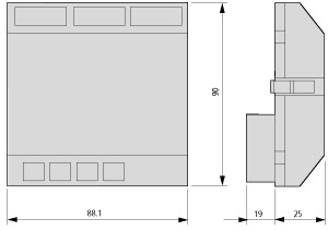
Dimensions (W x H x D)
89 x 90 x 25 (installed) mm
Weight
0.114 kg
Mounting
Fitted into the power supply unit.
Terminal capacities
Solid
0.2⁄4 (AWG 24 - 12) mm2
Flexible with ferrule
0.2⁄2.5 (AWG 24 - 12) mm2
Standard screwdriver
3.5 x 0.6 mm
Climatic environmental conditions
Operating ambient temperature
-25 to 55, cold as per IEC 60068-2-1, heat as per IEC 60068-2-2 °C
Condensation
Take appropriate measures to prevent condensation
Storage
- 40 - 70 °C
Relative humidity, non-condensing (IEC/EN 60068-2-30)
5 - 95 %
Air pressure (operation)
795 - 1080 hPa
Ambient conditions, mechanical
Pollution degree
2
Protection type (IEC/EN 60529, EN50178, VBG 4)
IP20
Vibrations (IEC/EN 60068-2-6)Constant amplitude 0.15 mm
10 - 57 Hz
Vibrations (IEC/EN 60068-2-6)Constant acceleration 2 g
57 - 150 Hz
Mechanical shock resistance (IEC/EN 60068-2-27) semi-sinusoidal 15 g/11 ms
18 Impacts
Drop to IEC/EN 60068-2-31 [Drop height]
50 mm
Free fall, packaged (IEC/EN 60068-2-32)
1 m
Mounting position
Vertical or horizontal
Electromagnetic compatibility (EMC)
Electrostatic discharge (IEC/EN 61000-4-2, Level 3, ESD)Air discharge
8 kV
Electrostatic discharge (IEC/EN 61000-4-2, Level 3, ESD)Contact discharge
6 kV
Electromagnetic fields (RFI) to IEC EN 61000-4-3
10 V/m
Radio interference suppression
EN 55011 Class B, EN 55022 Class B
Burst Impulse (IEC/EN 61000-4-4, Level 3)Supply cable
2 kV
Burst Impulse (IEC/EN 61000-4-4, Level 3)Signal lines
2 kV
Power pulses (surge) (IEC/EN 61000-4-5)
2 (supply cables, symmetrical) kV
power pulses (surge) (IEC/EN 61000-4-5, level 2)
0.5 (symmetrical power lines) kV
Immunity to line-conducted interference to (IEC/EN 61000-4-6)
10 V
Insulation resistance
Clearance in air and creepage distances
EN 50178, UL 508, CSA C22.2, No. 142
Insulation resistance
EN 50178
Power supply
Heat dissipation
2 W
Digital inputs 24 V DC
Number
12
Inputs can be used as analog inputs
4 (I7, I8, I11, I12)
Potential isolationFrom power supply
No
Potential isolationBetween digital inputs
No
Potential isolationFrom the outputs
Yes
Potential isolationto PC interface, memory card, easyNet, easyLink
Yes
Rated operational voltage [Ue]
24 V DC
On 0 signal [Ue]
< 5.0 (I1 - I6, I9 - I10) < 8 (I7, I8, I11, I12) V DC
On 1 signal [Ue]
< 5.0 (I1 - I6, I9 - I10) < 8 (I7, I8, I11, I12) V DC
Input current on 1 signalI1 to I6
3.3 (at 24 V DC) mA
Input current on 1 signalI7, I8
2.2 (at 24 V DC) mA
Input current on 1 signalI9, I10
3.3 (at 24 V DC) mA
Input current on 1 signalI11, I12
2.2 (at 24 V DC) mA
Delay time from 0 to 1Debounce ON
20 ms
Delay time from 0 to 1Debounce OFF
Normally 0.025 (I1 - I4), normally 0.25 (I5, I6, I9, I10), normally 0.15 (I7, I8, I11, I12) ms
Delay time from 1 to 0Debounce ON
20 ms
Delay time from 1 to 0Debounce OFF
Normally 0.025 (I1 - I4), normally 0.25 (I5, I6, I9, I10), normally 0.15 (I7, I8, I11, I12) ms
Cable length (unscreened)
100 m
Frequency counterQuantity
4 (I1, I2, I3, I4)
Frequency counterCounter frequency
< 3 kHz
Frequency counterPulse shape
Square
Frequency counterPulse pause ratio
01:01
Incremental counterQuantity
2 (I1 + I2, I3 + I4)
Incremental counterCounter frequency
≦ 3 kHz
Incremental counterPulse shape
Square
Incremental counterSignal offset
90°
Incremental counterPulse pause ratio
01:01
Rapid counter inputsNumber
4 (I1, I2, I3, I4)
Rapid counter inputsCounter frequency
< 3 kHz
Rapid counter inputsPulse shape
Square
Rapid counter inputsPulse pause ratio
01:01
Cable length, screened
< 20 m
Analog inputs
Number
1
Potential isolationFrom power supply
No
Potential isolationFrom the digital inputs
No
Potential isolationFrom the outputs
Yes
Potential isolationFrom the PC interface, memory card NET network, EASY-Link
Yes
Input type
DC voltage
Signal range
0 - 10 V DC
Resolution, analog
0.01 V
Resolution, digital
0.01 V
Resolution
10 (value 0 - 1023) Bit
Input impedance
11.2 kΩ
Accuracy of actual valuetwo MFD devices
± 3 %
Accuracy of actual valueWithin a single device
± 2 %
Conversion time, analog/digital
Every CPU cycle ms
Input current
< 1 mA
Cable length screened
< 30 m
Analog inputs temperature resistance Pt100 or Ni1000 sensors
Potential isolationFrom power supply
No
Potential isolationFrom the digital inputs
No
Potential isolationFrom the outputs
Yes
Relay outputs
Potential isolationFrom power supply
Yes
Transistor outputs
Number
4
Rated operational voltage [Ue]
24 V DC
Admissible range [Ue]
20.4 - 28.8 V DC
Supply currentOn 0 signal [Normally⁄max.]
18/32 mA
Supply currentOn 1 signal [Normally⁄max.]
24 /44 mA
Protection against polarity reversal
yes (Caution: A short circuit will result if 0 V or earth is applied to the outputs in the event that the supply voltage is connected to the wrong poles.)
Potential isolationPotential isolation of the power supply, inputs
Yes
Potential isolationFrom the inputs
Yes
Potential isolationto PC interface, memory card, easyNet, easyLink
Yes
Rated operational current at signal „1” DC per channel [Ie]
max. 0.5 A
Lamp load without Rvper channel
5 (Q1 - Q4) W
Residual current on 0 signal per channel
< 0.1 mA
Max. output voltageOn 0 signal with external load < 10 MΩ
2.5 V
Max. output voltageOn 1 signal with Ie= 0.5 A
U = Ue-1 V V
Short-circuit protection
Thermal (Q1 - Q4), (evaluation with diagnostics input I16)
Short-circuit tripping current for Ra≦ 10 mΩ
0.7 ≦ Ie≦ 2 per output A
Total short-circuit current
8 A
Peak short-circuit current
16 A
Thermal cutout
Yes
Max. operating frequency with constant resistive load
40000 Operations/h
Parallel connection of outputsWith resistive load, inductive load with external suppressor circuit, combination within a group
Group 1: Q1 to Q4
Parallel connection of outputsNumber of outputs [max.]
4
Parallel connection of outputsTotal max. current
2 (Caution! Outputs must be switched simultaneously and for the same period.) A
Inductive load to EN 60947-5-1Without external suppressor circuitT0.95 = 1 ms, R = 48 Ω, L = 16 mHUtilization factor
0.25 g
Inductive load to EN 60947-5-1Without external suppressor circuitT0.95 = 1 ms, R = 48 Ω, L = 16 mHDuty factor
100 % DF
Inductive load to EN 60947-5-1Without external suppressor circuitT0.95 = 1 ms, R = 48 Ω, L = 16 mHMax. switching frequency f = 0.5 Hz (max. DF = 50 %)
1500 Operations
Inductive load to EN 60947-5-1Without external suppressor circuitDC-13, T0.95 = 72 ms, R = 48 Ω, L = 1.15 HUtilization factor
0.25 g
Inductive load to EN 60947-5-1Without external suppressor circuitDC-13, T0.95 = 72 ms, R = 48 Ω, L = 1.15 HDuty factor
100 % DF
Inductive load to EN 60947-5-1Without external suppressor circuitDC-13, T0.95 = 72 ms, R = 48 Ω, L = 1.15 HMax. switching frequency f = 0.5 Hz (max. DF = 50 %)
1500 Operations
Inductive load to EN 60947-5-1Without external suppressor circuitT0.95 = 15 ms, R = 48 Ω, L = 0.24 HUtilization factor
0.25 g
Inductive load to EN 60947-5-1Without external suppressor circuitT0.95 = 15 ms, R = 48 Ω, L = 0.24 HDuty factor
100 % DF
Inductive load to EN 60947-5-1Without external suppressor circuitT0.95 = 15 ms, R = 48 Ω, L = 0.24 HMax. switching frequency f = 0.5 Hz (max. DF = 50 %)
1500 Operations
Inductive load to EN 60947-5-1With external suppressor circuitUtilization factor
1 g
Inductive load to EN 60947-5-1With external suppressor circuitDuty factor
100 % DF
Inductive load to EN 60947-5-1With external suppressor circuitMax. switching frequency, max. duty factor
Depending on the suppressor circuit Operations
Design verification as per IEC/EN 61439
Technical data for design verification
Rated operational current for specified heat dissipation [In]
0 A
Heat dissipation per pole, current-dependent [Pvid]
0 W
Equipment heat dissipation, current-dependent [Pvid]
0 W
Static heat dissipation, non-current-dependent [Pvs]
2 W
Heat dissipation capacity [Pdiss]
0 W
Operating ambient temperature min.
-25 °C
Operating ambient temperature max.
+55 °C
IEC/EN 61439 design verification
10.2 Strength of materials and parts10.2.2 Corrosion resistance
Meets the product standard's requirements.
10.2 Strength of materials and parts10.2.3.1 Verification of thermal stability of enclosures
Meets the product standard's requirements.
10.2 Strength of materials and parts10.2.3.2 Verification of resistance of insulating materials to normal heat
Meets the product standard's requirements.
10.2 Strength of materials and parts10.2.3.3 Verification of resistance of insulating materials to abnormal heat and fire due to internal electric effects
Meets the product standard's requirements.
10.2 Strength of materials and parts10.2.4 Resistance to ultra-violet (UV) radiation
Meets the product standard's requirements.
10.2 Strength of materials and parts10.2.5 Lifting
Does not apply, since the entire switchgear needs to be evaluated.
10.2 Strength of materials and parts10.2.6 Mechanical impact
Does not apply, since the entire switchgear needs to be evaluated.
10.2 Strength of materials and parts10.2.7 Inscriptions
Meets the product standard's requirements.
10.3 Degree of protection of ASSEMBLIES
Meets the product standard's requirements.
10.4 Clearances and creepage distances
Meets the product standard's requirements.
10.5 Protection against electric shock
Does not apply, since the entire switchgear needs to be evaluated.
10.6 Incorporation of switching devices and components
Does not apply, since the entire switchgear needs to be evaluated.
10.7 Internal electrical circuits and connections
Is the panel builder's responsibility.
10.8 Connections for external conductors
Is the panel builder's responsibility.
10.9 Insulation properties10.9.2 Power-frequency electric strength
Is the panel builder's responsibility.
10.9 Insulation properties10.9.3 Impulse withstand voltage
Is the panel builder's responsibility.
10.9 Insulation properties10.9.4 Testing of enclosures made of insulating material
Is the panel builder's responsibility.
10.10 Temperature rise
The panel builder is responsible for the temperature rise calculation. Eaton will provide heat dissipation data for the devices.
10.11 Short-circuit rating
Is the panel builder's responsibility.
10.12 Electromagnetic compatibility
Is the panel builder's responsibility.
10.13 Mechanical function
The device meets the requirements, provided the information in the instruction leaflet (IL) is observed.
Technical data ETIM 7.0
PLC's (EG000024) / PLC digital I/O-module (EC001419)
Electric engineering, automation, process control engineering / Control / Programmable logic control (SPS) / SPS digital input/output module ([email protected] [AKE527014])
Supply voltage AC 50 Hz
0 - 0 V
Supply voltage AC 60 Hz
0 - 0 V
Supply voltage DC
20.4 - 28.8 V
Voltage type of supply voltage
DC
Number of digital inputs
12
Number of digital outputs
4
Digital inputs configurable
No
Digital outputs configurable
No
Input current at signal 1
3.3 mA
Permitted voltage at input
20.4 - 28.8 V
Type of voltage (input voltage)
DC
Type of digital output
Transistor
Output current
0.5 A
Permitted voltage at output
20.4 - 28.8 V
Type of output voltage
DC
Short-circuit protection, outputs available
Yes
Redundancy
No
Type of electric connection
Spring clamp connection
Time delay at signal exchange
0.1 - 20 ms
Suitable for safety functions
No
Category according to EN 954-1
SIL according to IEC 61508
None
Performance level acc. EN ISO 13849-1
None
Appendant operation agent (Ex ia)
No
Appendant operation agent (Ex ib)
No
Explosion safety category for gas
None
Explosion safety category for dust
None
Width
89 mm
Height
90 mm
Depth
25 mm
Approvals
Product Standards
IEC/EN see Technical Data; UL 508; CSA C22.2 No. 142-M1987; CSA C22.2 No. 213-M1987; CE marking
UL File No.
E135462
UL Category Control No.
NRAQ
CSA File No.
012528
CSA Class No.
2252-01 + 2258-02
North America Certification
UL listed, CSA certified
Degree of Protection
IEC: IP20, UL/CSA Type: -
Dimensions
Datasheet - PDF
▲| Title: | Size: | Type: |
|---|---|---|
| PDF EATON SAFETY LOGIC EN.pdf | 2 Mbytes |

|
| PDF CATALOGUE EATON EN.pdf | 51 Mbytes |
|
| MFD-T16 0004519705 265255 EN_265255.pdf | 221 Kbytes |
|
Reviews (0) ▲
No customer reviews for the moment.
Add Review
hide form
| Rating: |
|
| Name: | |
| Email: | |
| Subject: | |
| Text: | |
| Do you recommend this product to buy? | |
|
|
|
| Add review | |
All ratings we receive from the items we offer are real and verified. A small gesture, but a lot of value. That's why we thank you for that minute you invest in leaving us your opinion and qualification about the products, because it helps us to continue improving and to offer you a service of even higher quality.