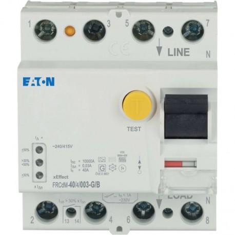
Special features
- Current test marks as per inscription
- Dry auxiliary contact: > 100,000 electrical switching operations per minute at 2 A 30 VDC resistive load
- Dry auxiliary contact: > 5 x 100,000 electrical switching operations per minute at 1 A 30 VDC resistive load
- Maximum operating temperature is 60 °C in accordance with the de-rating table
Application
- Switchgear for industrial and advanced commercial applications
- xEffect - Switchgear for industrial and advanced commercial applications
Features
Residual current circuit-breakers, digital
Additional equipment possible
10.10 Temperature rise
The panel builder is responsible for the temperature rise calculation. Eaton will provide heat dissipation data for the devices.
10.11 Short-circuit rating
Is the panel builder's responsibility. The specifications for the switchgear must be observed.
10.12 Electromagnetic compatibility
Is the panel builder's responsibility. The specifications for the switchgear must be observed.
10.13 Mechanical function
The device meets the requirements, provided the information in the instruction leaflet (IL) is observed.
10.2.2 Corrosion resistance
Meets the product standard's requirements.
10.2.3.1 Verification of thermal stability of enclosures
Meets the product standard's requirements.
10.2.3.2 Verification of resistance of insulating materials to normal heat
Meets the product standard's requirements.
10.2.3.3 Resist. of insul. mat. to abnormal heat/fire by internal elect. effects
Meets the product standard's requirements.
10.2.4 Resistance to ultra-violet (UV) radiation
Meets the product standard's requirements.
10.2.5 Lifting
Does not apply, since the entire switchgear needs to be evaluated.
10.2.6 Mechanical impact
Does not apply, since the entire switchgear needs to be evaluated.
10.2.7 Inscriptions
Meets the product standard's requirements.
10.3 Degree of protection of assemblies
Does not apply, since the entire switchgear needs to be evaluated.
10.4 Clearances and creepage distances
Meets the product standard's requirements.
10.5 Protection against electric shock
Does not apply, since the entire switchgear needs to be evaluated.
10.6 Incorporation of switching devices and components
Does not apply, since the entire switchgear needs to be evaluated.
10.7 Internal electrical circuits and connections
Is the panel builder's responsibility.
10.8 Connections for external conductors
Is the panel builder's responsibility.
10.9.2 Power-frequency electric strength
Is the panel builder's responsibility.
10.9.3 Impulse withstand voltage
Is the panel builder's responsibility.
10.9.4 Testing of enclosures made of insulating material
Is the panel builder's responsibility.
Used with
Residual current circuit-breakers, digital
FRCdM
Type G/B (ÖVE E 8601)
Mounting Method
DIN rail
Quick attachment with 2 latch positions for DIN-rail IEC/EN 60715
Climatic proofing
25-55 °C / 90-95% relative humidity according to IEC 60068-2
Equipment heat dissipation, current-dependent
Rated impulse withstand voltage (Uimp)
Rated short-time withstand current (Icw)
Admissible back-up fuse overload - max
Built-in width (number of units)
Busbar material thickness
Short-circuit rating
63 A (max. admissible back-up fuse)
Switching capacity of auxiliary contact - min
Terminal protection
Finger and hand touch safe, DGUV VS3, EN 50274
Terminals (top and bottom)
Ambient operating temperature - max
Ambient operating temperature - min
Connectable conductor cross section (multi-wired) - max
Connectable conductor cross section (multi-wired) - min
Connectable conductor cross section (solid-core) - max
Connectable conductor cross section (solid-core) - min
Heat dissipation capacity
Heat dissipation per pole, current-dependent
Permitted storage and transport temperature - max
Permitted storage and transport temperature - min
Contact position indicator color
Degree of protection
IP20, IP40 with suitable enclosure
IP20
Impulse withstand current
3 kA (8/20 μs) surge-proof
Functions
Short-time delayed tripping
Terminal capacity (cable)
M5 (with cross-recessed screw as defined in EN ISO 4757-Z2, PZ2)
Rated fault current - max
Rated fault current - min
Rated insulation voltage (Ui)
Rated operational current for specified heat dissipation (In)
Rated operational voltage (Ue) - max
Rated residual making and breaking capacity
Rated switching capacity (resistive load) of auxiliary contact at 240 V AC
Rated switching capacity (resistive load) of auxiliary contact at 30 V DC
Static heat dissipation, non-current-dependent
Switching current of auxiliary contact - max
Switching duty with resistive load of auxiliary contact - max
Switching voltage at AC of auxiliary contact - max
Switching voltage at DC of auxiliary contact - max
Width in number of modular spacings
Voltage rating (IEC/EN 60947-2)
Terminal capacity (solid wire)
Tripping time
10 ms delayed
Short time-delayed
Rated short-circuit strength
Terminal capacity (stranded cable)
Terminal capacity of auxiliary contact
 Ver maior


