
Ningún producto
Producto añadido correctamente a su carrito de la compra



















































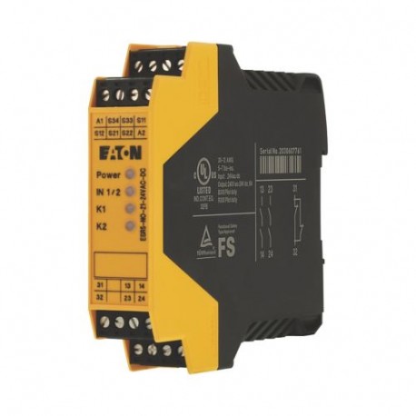 Ver más grande
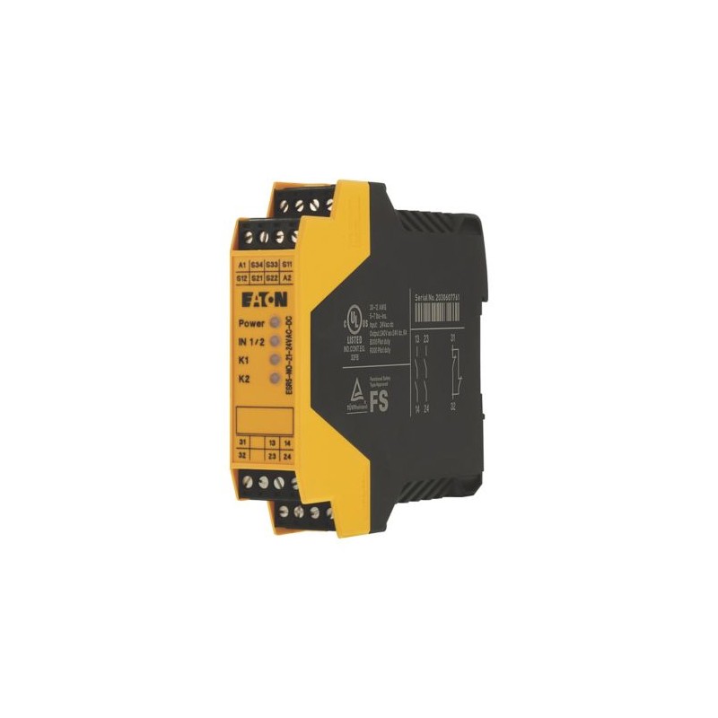
ESR5-NO-21-24VAC-DC 118700 Y7-118700 EATON ELECTRIC Relé de seguridad Parada de emergencia, Puerta de seguri..
ESR5-NO-21-24VAC-DC
118700
Y7-118700
EATON-MOELLER
Relé de seguridad; Parada de emergencia, Puerta de seguridad; 24 V DC/AC; 2 Rutas de validación
Relé de seguridad. Parada de emergencia, Puerta de seguridad. 24 V DC/AC.
Eaton ESR5 Safety relay emergency stop/protective door, 24VDC/AC, 2 enabling paths
Relé de seguridad de doble canal, para la implementación de las funciones básicas desconexión de emergencia, parada de emergencia y puerta de protección, tensión de alimentación 24VDC o 24VAC 50/60Hz, 2 rutas de corriente de habilitación (IEC/EN 60204 Categoría de parada 0), 1 ruta de corriente de señal, cubierta de etiqueta de barra colectora según EN 50274 con accionamiento vertical desde la parte delantera a prueba de dedos y dorso de la mano, apto para cat. 4 según EN 954-1 / PL e según EN ISO 13849-1 / SILCL 3 según IEC 62061 / SIL 3 según IEC 61508, grado de protección IP20, lugar de instalación IP54 mínimo, probado por TÜV, tensión de impulso nominal 6 kV / aislamiento seguro, aislamiento reforzado
Relés > Dispositivo de vigilancia de circuitos de seguridad
Relés temporizadores (KETR, KEMR, KESR)
Producto nuevo en su embalaje original con todas las garantías y certificaciones de EATON-MOELLER
Comprados juntos habitualmente
▲Más vendidos
▲Más Información
▲Especificaciones generales
UL
UL 508
IEC/EN 60204
UL report applies to both US and Canada
UL File No.: E29184
Certified by UL for use in Canada
CSA-C22.2 No. 14-95
EN 50178
CE
IEC 62061
2014/30/EU
CSA Class No.: 3211-83; 3211-03
EN ISO 13849-1
UL Category Control No.: NKCR; NKCR7
Machines 2006/42/EG
Feature & Functions
Reinforced insulation
Safe insulation
Automatic reset
Approval for TÜV
Detachable clamps
Feedback circuit
Start input
2-channel
Contacts: silver tin oxide, gold plated (AgSnO2, 0.2 µm Au)
General information
65 mA, DC
Terminals: IP20
Enclosure: IP20
IP20
According to EN-61000-6-2
Top-hat rail fixing (according to IEC/EN 60715, 35 mm)
SIL 3, Safety integrity level, In accordance with IEC 61508
Cat. 4, Category
SILCL 3, Safety integrity level claim limit
5.05 x 10⁻¹⁰, PFHd, Probability of failure per hour
Safety relay for monitoring emergency stop and protective door switch
Monitoring of emergency-stop circuits
Module used to safely interrupt electrical circuits
Ambient conditions, mechanical
66 Months (Low Demand)
4 A at 360 O/h, DC-13 at 24 V, Outputs
2.5 A at 3600 O/h, DC-13 at 24 V, Outputs
0.4 W
In accordance with IEC 60947-5-1, Outputs
4 A at 360 O/h, AC-15 at 230 V, Outputs
Climatic environmental conditions
Cold to EN 60068-2-1
Damp heat, constant, to IEC 60068-2-3
Condensation: Non-condensing
Terminal capacities
2 x (0.2 – 1) mm², solid
1 x (0.2 – 2.5) mm², solid
2 x (0.25 – 1) mm², flexible with ferrule
1 x (0.25 – 2.5) mm², flexible with ferrule
0.6 x 3.5 mm, Terminal screws
Electrical rating
3.4 W (AC operated 50/60 Hz)
230 V AC
24 V AC/DC (power supply)
Fuse 6 A gL/gG, For output circuits, External
10A gL/gG, NEOZED (N/O), Output fuse, External, Output data
Input/Output
1500 VA, max., resistive load (τ = 0 ms), at 250 V AC
35 W max., inductive load (τ = 40 ms), at 220 V DC
48 W max., inductive load (τ = 40 ms), at 24 V DC
288 W max., resistive load (τ = 0 ms), at 48 V DC
35 W max., inductive load (τ = 40 ms), at 110 V DC
40 W max., inductive load (τ = 40 ms), at 48 V DC
77 W max., resistive load (τ = 0 ms), at 110 V DC
88 W max., resistive load (τ = 0 ms), at 220 V DC
100 ms typ. (K1, K2 - for UN automatic mode)
45 ms (single-channel)
6 A N/C, Limiting continuous current
Design verification
| Característica | Valor |
|---|---|
| Modelo (EF000010) | Basic device |
| Montaje en carril posible (EF003972) | true |
| Con abrazaderas extraíbles (EF003340) | true |
| Ejecución de la conexión eléctrica (EF003961) | Screw connection |
| Tipo de tensión de alimentación (EF002991) | AC/DC |
| Tensión de alimentación 50 Hz CA (EF007532) | 24 V |
| Tensión de alimentación 60 Hz CA (EF007533) | 24 V |
| Tensión de alimentación CC (EF007534) | 24 V |
| Apto para la supervisión de interruptores de posición (EF007270) | true |
| Apto para la supervisión de circuitos de parada de emergencia (EF007268) | true |
| Apto para la supervisión de válvulas (EF007272) | false |
| Apto para el control de dispositivos de protección optoelectrónicos (EF007269) | false |
| Apto para la supervisión de sensores táctiles (EF007271) | false |
| Apto para la supervisión de interruptores magnéticos (EF007266) | false |
| Apto para la supervisión de interruptores de proximidad (EF007267) | false |
| Evaluación de las entradas (EF008245) | 1-channel |
| Consumo de energía (EF000346) | 5.16 W |
| Con entrada de inicio (EF003342) | true |
| Con función de silenciamiento (EF004057) | false |
| Con circuito de realimentación (EF003343) | true |
| Retardo de liberación (EF001129) | 0 s |
| Tipo de tensión de control 1 (EF002954) | AC/DC |
| Tensión de control 1 (EF002952) | 24 V |
| Tipo de tensión de control 2 (EF002955) | AC/DC |
| Tensión de control 2 (EF002953) | 24 V |
| Número de salidas, de seguridad, instantáneas, basadas en contactos (EF003344) | 2 |
| Número de salidas, de seguridad, retardadas, basadas en contactos (EF003345) | 0 |
| Número de salidas, relacionadas con la seguridad, instantáneas, semiconductores (EF003346) | 0 |
| Número de salidas, relacionadas con la seguridad, retardadas, semiconductores (EF003347) | 0 |
| Número de salidas, función de señalización, instantánea, basada en contactos (EF003348) | 1 |
| Número de salidas, función de señalización, retardado, basado en contacto (EF003349) | 0 |
| Número de salidas, función de señalización, instantánea, semiconductores (EF003350) | 0 |
| Número de salidas, función de señalización, retardado, semiconductores (EF003351) | 0 |
| Tipo de tensión de funcionamiento (EF005294) | AC/DC |
| Voltaje de funcionamiento a 50 Hz CA (EF008206) | 24 V |
| Voltaje de funcionamiento a 60 Hz CA (EF008207) | 24 V |
| Voltaje de funcionamiento en CC (EF008208) | 24 V |
| Corriente nominal de conmutación (EF006706) | 4 A |
| Tipo de seguridad según IEC 61496-1 (EF004105) | None |
| Categoría de parada según IEC 60204 (EF007498) | 0 |
| Nivel de rendimiento según EN ISO 13849-1 (EF007399) | Level e |
| SIL según IEC 61508 (EF009889) | 3 |
| Con aprobación para BG BIA (EF004145) | false |
| Con aprobación según UL (EF001783) | true |
| Anchura (EF000008) | 22.5 mm |
| Altura (EF000040) | 99 mm |
| Profundidad (EF000049) | 114.5 mm |
| With approval for TÜV (EFDE0031) | true |
Datasheet - PDF
▲| Título: | Tamaño: | Tipo: |
|---|---|---|
| PDF CATALOGO EATON AUTOMATIZACION ES.pdf | 19 Mbytes |

|
| PDF CATALOGO EATON CONTROL Y AUTOMATIZACION ES.pdf | 9 Mbytes |
|
| PDF CATALOGUE EATON EN .pdf | 38 Mbytes |
|
| ESR5-NO-21-24VAC-DC Y7-118700 118700 ES_118700.pdf | 718 Kbytes |
|
Opiniones: (0) ▲
Ningún comentario por el momento.
| Valoración: |

|
| Nombre: | |
| Email: | |
| Título: | |
| Opinión: | |
| ¿Recomienda la compra de este producto? | |
|
|
|
| Añadir comentario | |
Todas las valoraciones que recibimos de los artículos que ofrecemos son reales y están verificadas. Un pequeño gesto, pero de mucho valor. Por eso, te agradecemos ese minuto que inviertes en dejarnos tu opinión y calificación sobre los productos, porque nos ayuda a seguir mejorando y a ofrecerte un servicio de todavía mayor calidad.