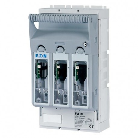
XNH00-FCL-A160-BT 183028 0001624003 EATON ELECTRIC NH fuse-switch 3p box terminal 1,5 95 mm² mounting plate .. View larger
Images are for illustrative purposes only. Please refer to data sheet for details.

XNH00-FCL-A160-BT 183028 0001624003 EATON ELECTRIC NH fuse-switch 3p box terminal 1,5 95 mm² mounting plate ..

XNH00-FCL-A160-BT

183028

0001624003

EATON-MOELLER

NH fuse-switch 3p box terminal 1,5 - 95 mm²; mounting plate; light fuse monitoring; NH000 & NH00

XNH00-FCL-A160-BT

More details


Low-voltage industrial components > Fuse switch disconnector

Industrial Fuse Bases

* Brand new product in its original packaging covered by the warranties and certifications provided by EATON-MOELLER

Total price: $174.22
Unit price: $174.22

Quantity Price
1+$174.22
2+$162.19
3+$162.19
*This price is per unit and is the net value (not including taxes if applicable).

If our price is not the best, please ask us for a quote. Ask for a quotation

Best sellers

More info


EL-Nummer (Norway)
0001624003
NH fuse-switch 3p box terminal 1,5 - 95 mm²; mounting plate; light fuse monitoring; NH000 & NH00
NH fuse switch-disconnector 3 pole with box terminal 1,5 - 95 mm²; mounting plate; light fuse monitoring with LED; for NH000 & NH00 fuse-links; optionally lockable with XNH-XLOCK and padlock

Delivery program

Basic function
Fuse control - light
Number of poles
3 pole
Mounting type
DIN rails
Mounting plate
Size
00
Type of connection
Box terminal
Rated operational current [Ie]
160 A
Front degree of protection (XNH installed)
IP20 (Operating status)
IP2XC (Contact protection)
IP10 (Handle cover open)
Rated operational voltage [Ue]
690 V AC
Rated operational voltage [Ue]
440 V DC
Rated conditional short-circuit current
120 (500 V)
100 (690 V) kA
Flammability characteristics
Self-extinguishing as per UL 94
Description
Current paths of electrolytic copper, silver-plated
With optical signalling of triggered fuse-links

Technical data

Electrical
Standards
IEC/EN 60947-3
Rated operational voltage [Ue]
690 V AC
Rated operational voltage [Ue]
440 V DC
Rated operational current [Ie]
160 A
Rated frequency [f]
40 - 60 Hz
Rated insulation voltage [Ui]
800 V AC
Total heat dissipation at Ith(without fuses) [Pv]
9 W
Heat dissipation at 80% (without fuses) [Pv]
5.8 W
Rated impulse withstand voltage [Uimp]
8 kV
Utilization category AC-23BRated operating voltage [Ue]
400 V AC
Utilization category AC-23BRated operating current [Ie]
160 A
Utilization category AC­22BRated operating voltage [Ue]
500 V AC
Utilization category AC­22BRated operating current [Ie]
160 A
Utilization category AC-21BRated operating voltage [Ue]
690 V AC
Utilization category AC-21BRated operating current [Ie]
160 A
Utilization category DC-22BRated operating voltage [Ue]
250 V DC
Utilization category DC-22BRated operating current [Ie]
160 A
Utilization category DC­21BRated operating voltage [Ue]
440 V DC
Utilization category DC­21BRated operating current [Ie]
160 A
Rated conditional short-circuit current
120 (500 V)
100 (690 V) kA
Rated short-time withstand current [Icw]
7 kA
Max. fuseSize according to DIN VDE 0636-2
000 / 00
Max. fuseMax. permitted power loss per fuse link [Pv]
12 W
Lifespan, electrical [Operations]
300
Mechanical
Front degree of protection (XNH installed)
IP20 (Operating status)
IP2XC (Contact protection)
IP10 (Handle cover open)
Ambient temperature
-25 - +55 °C
Rated operating mode
Permanent operation
Activation
Dependent manual activation
Mounting position
Vertical, horizontal
Altitude
Max. 2000 m
Overvoltage category/pollution degree
III/3
RoHS (in accordance with Directive 2002/95/EC of the European Parliament and Council)
Yes
Direction of incoming supply
as required
Lockable
Yes, optional
Sealable
Yes, Standard
Material characteristicsMaterial
Polyamide
Material characteristicsColour
Grey
Flammability characteristics
Self-extinguishing as per UL 94
Halogen-free
Yes
Voltage test
Yes, sliding inspection windows
Lifespan, mechanical [Operations]
1400
Track resistance
CTI 600
Heat deflection temperature
125 °C
Terminal capacity
Flange connectionBolt diameter
M8
Flange connectionCable lug max. width
25 mm
Flange connectionFlat busbar
20 x 10 mm
Box terminalStranded
1,5 - 95 Cu mm2
Box terminalCopper strip [Number of segments x width x thickness]
9 x 9 x 0,8 mm
Box terminalStranded
1,5 - 50 Cu mm2
Box terminalCopper band [Number of segments x width x thickness ]
6 x 9 x 0,8 mm
Clamp-type terminalStranded
10 - 70 Cu/Al mm2
Double clamp-type terminalStranded
- mm2

Design verification as per IEC/EN 61439

Technical data for design verification
Rated operational current for specified heat dissipation [In]
160 A
Heat dissipation per pole, current-dependent [Pvid]
3 W
Equipment heat dissipation, current-dependent [Pvid]
9 W
IEC/EN 61439 design verification
10.2 Strength of materials and parts10.2.2 Corrosion resistance
Meets the product standard's requirements.
10.2 Strength of materials and parts10.2.3.1 Verification of thermal stability of enclosures
Meets the product standard's requirements.
10.2 Strength of materials and parts10.2.3.2 Verification of resistance of insulating materials to normal heat
Meets the product standard's requirements.
10.2 Strength of materials and parts10.2.3.3 Verification of resistance of insulating materials to abnormal heat and fire due to internal electric effects
Meets the product standard's requirements.
10.2 Strength of materials and parts10.2.4 Resistance to ultra-violet (UV) radiation
Meets the product standard's requirements.
10.2 Strength of materials and parts10.2.5 Lifting
Does not apply, since the entire switchgear needs to be evaluated.
10.2 Strength of materials and parts10.2.6 Mechanical impact
Does not apply, since the entire switchgear needs to be evaluated.
10.2 Strength of materials and parts10.2.7 Inscriptions
Meets the product standard's requirements.
10.3 Degree of protection of ASSEMBLIES
Does not apply, since the entire switchgear needs to be evaluated.
10.4 Clearances and creepage distances
Is the panel builder's responsibility.
10.5 Protection against electric shock
Does not apply, since the entire switchgear needs to be evaluated.
10.6 Incorporation of switching devices and components
Does not apply, since the entire switchgear needs to be evaluated.
10.7 Internal electrical circuits and connections
Is the panel builder's responsibility.
10.8 Connections for external conductors
Is the panel builder's responsibility.
10.9 Insulation properties10.9.2 Power-frequency electric strength
Ui= 800 V AC
10.9 Insulation properties10.9.3 Impulse withstand voltage
Is the panel builder's responsibility.
10.9 Insulation properties10.9.4 Testing of enclosures made of insulating material
Is the panel builder's responsibility.
10.10 Temperature rise
The panel builder is responsible for the temperature rise calculation. Eaton will provide heat dissipation data for the devices.
10.11 Short-circuit rating
Is the panel builder's responsibility. The specifications for the switchgear must be observed.
10.12 Electromagnetic compatibility
Is the panel builder's responsibility. The specifications for the switchgear must be observed.
10.13 Mechanical function
The device meets the requirements, provided the information in the instruction leaflet (IL) is observed.

Technical data ETIM 7.0

Low-voltage industrial components (EG000017) / Fuse switch disconnector (EC001040)
Electric engineering, automation, process control engineering / Low-voltage switch technology / Off-load switch, circuit breaker, control switch / Fuse switch disconnector ([email protected] [AKF058013])
Version as main switch
No
Version as safety switch
No
Max. rated operation voltage Ue AC
690 V
Rated permanent current Iu
160 A
Rated operation power at AC-23, 400 V
0 kW
Conditioned rated short-circuit current Iq
120 kA
Rated short-time withstand current lcw
7 kA
Suitable for fuses
NH00
Number of poles
3
With error protection
Yes
Type of electrical connection of main circuit
Frame clamp
Cable entry
Other
Equipped with connectors
No
Suitable for ground mounting
Yes
Suitable for front mounting 4-hole
No
Suitable for busbar mounting
No
Type of control element
Cover grip
Position control element
Front side
Motor drive optional
No
Motor drive integrated
No
Version as emergency stop installation
No
Degree of protection (IP), front side
Other

Dimensions

1230DIM-352

Datasheet - PDF

Reviews (0)

No customer reviews for the moment.

Add Review
hide form
Rating:
Name:
Email:
Subject:
Text:
  Captcha
  Add review

All ratings we receive from the items we offer are real and verified. A small gesture, but a lot of value. That's why we thank you for that minute you invest in leaving us your opinion and qualification about the products, because it helps us to continue improving and to offer you a service of even higher quality.