Standards
IEC/EN 60947, VDE 0660, UL, CSA
Lifespan, mechanicalAC operated [Operations]
5 x 10⁶
Lifespan, mechanicalDC operated [Operations]
5 x 10⁶
Operating frequency, mechanicalAC operated [Operations/h]
1000
Operating frequency, mechanicalDC operated [Operations/h]
1000
Climatic proofing
Damp heat, constant, to IEC 60068-2-78
Damp heat, cyclic, to IEC 60068-2-30
Ambient temperatureOpen
-40 - +60 °C
Ambient temperatureStorage
- 40 - + 80 °C
Mechanical shock resistance (IEC/EN 60068-2-27)Half-sinusoidal shock, 10 msMain contactsN/O contact
10 g
Mechanical shock resistance (IEC/EN 60068-2-27)Half-sinusoidal shock, 10 msAuxiliary contactsN/O contact
10 g
Mechanical shock resistance (IEC/EN 60068-2-27)Half-sinusoidal shock, 10 msAuxiliary contactsN/C contact
8 g
Degree of Protection
IP00
Terminal capacity main cableBusbar [Width]
100 mm
Main cable connection screw/bolt
M12
Terminal capacity control circuit cablesSolid
1 x (0.75 - 2.5)
2 x (0.75 - 2.5) mm2
Terminal capacity control circuit cablesFlexible with ferrule
1 x (0.75 - 2.5)
2 x (0.75 - 2.5) mm2
Terminal capacity control circuit cablesSolid or stranded
18 - 14 AWG
Control circuit cable connection screw/bolt
M3.5
ToolMain cableWidth across flats
18 mm
ToolControl circuit cablesPozidriv screwdriver
2 Size
Rated impulse withstand voltage [Uimp]
8000 V AC
Overvoltage category/pollution degree
III/3
Rated insulation voltage [Ui]
1000 V AC
Rated operational voltage [Ue]
1000 V AC
Safe isolation to EN 61140between coil and contacts
500 V AC
Safe isolation to EN 61140between the contacts
500 V AC
Making capacity (p.f. to IEC/EN 60947)
19000 A
Breaking capacity220 V 230 V
16000 A
Breaking capacity380 V 400 V
16000 A
Breaking capacity500 V
16000 A
Breaking capacity660 V 690 V
16000 A
Breaking capacity1000 V
5800 A
Component lifespan
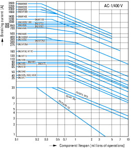
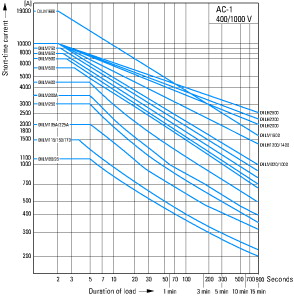
AC1: See → Engineering, characteristic curves
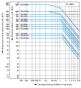
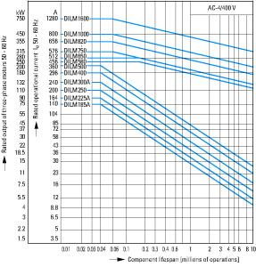
AC3: See → Engineering, characteristic curves
AC4: See → Engineering, characteristic curves
AC-1Rated operational currentConventional free air thermal current, 3 pole, 50 - 60 HzOpenat 40 °C [Ith=Ie]
2200 A
AC-1Rated operational currentConventional free air thermal current, 3 pole, 50 - 60 HzOpenat 50 °C [Ith=Ie]
1970 A
AC-1Rated operational currentConventional free air thermal current, 3 pole, 50 - 60 HzOpenat 55 °C [Ith=Ie]
1880 A
AC-1Rated operational currentConventional free air thermal current, 3 pole, 50 - 60 HzOpenat 60 °C [Ith=Ie]
1800 A
AC-1Rated operational currentConventional free air thermal current, 1 poleNote
at maximum permissible ambient air temperature
AC-1Rated operational currentConventional free air thermal current, 1 poleopen [Ith]
4500 A
AC-3Rated operational currentOpen, 3-pole: 50 – 60 HzNotes
At maximum permissible ambient temperature (open.)
AC-3Rated operational currentOpen, 3-pole: 50 – 60 Hz220 V 230 V [Ie]
1600 A
AC-3Rated operational currentOpen, 3-pole: 50 – 60 Hz240 V [Ie]
1600 A
AC-3Rated operational currentOpen, 3-pole: 50 – 60 Hz380 V 400 V [Ie]
1600 A
AC-3Rated operational currentOpen, 3-pole: 50 – 60 Hz415 V [Ie]
1600 A
AC-3Rated operational currentOpen, 3-pole: 50 – 60 Hz440V [Ie]
1600 A
AC-3Rated operational currentOpen, 3-pole: 50 – 60 Hz500 V [Ie]
1600 A
AC-3Rated operational currentOpen, 3-pole: 50 – 60 Hz660 V 690 V [Ie]
1600 A
AC-3Rated operational currentOpen, 3-pole: 50 – 60 Hz1000 V [Ie]
1200 A
AC-3Motor rating [P]220 V 230 V [P]
500 kW
AC-3Motor rating [P]240V [P]
550 kW
AC-3Motor rating [P]380 V 400 V [P]
900 kW
AC-3Motor rating [P]415 V [P]
930 kW
AC-3Motor rating [P]440 V [P]
1000 kW
AC-3Motor rating [P]500 V [P]
1180 kW
AC-3Motor rating [P]660 V 690 V [P]
1600 kW
AC-3Motor rating [P]1000 V [P]
1770 kW
AC-4Rated operational currentOpen, 3-pole: 50 – 60 Hz220 V 230 V [Ie]
1280 A
AC-4Rated operational currentOpen, 3-pole: 50 – 60 Hz240 V [Ie]
1280 A
AC-4Rated operational currentOpen, 3-pole: 50 – 60 Hz380 V 400 V [Ie]
1280 A
AC-4Rated operational currentOpen, 3-pole: 50 – 60 Hz415 V [Ie]
1280 A
AC-4Rated operational currentOpen, 3-pole: 50 – 60 Hz440 V [Ie]
1280 A
AC-4Rated operational currentOpen, 3-pole: 50 – 60 Hz500 V [Ie]
1280 A
AC-4Rated operational currentOpen, 3-pole: 50 – 60 Hz660 V 690 V [Ie]
1280 A
AC-4Rated operational currentOpen, 3-pole: 50 – 60 Hz1000 V [Ie]
1120 A
AC-4Motor rating [P]220 V 230 V [P]
430 kW
AC-4Motor rating [P]240 V [P]
450 kW
AC-4Motor rating [P]380 V 400 V [P]
750 kW
AC-4Motor rating [P]415 V [P]
770 kW
AC-4Motor rating [P]440 V [P]
830 kW
AC-4Motor rating [P]500 V [P]
940 kW
AC-4Motor rating [P]660 V 690 V [P]
1300 kW
AC-4Motor rating [P]1000 V [P]
1650 kW
3 pole, at Ith(60°)
155 W
Current heat loss at Ieto AC-3/400 V
123 W
Voltage toleranceUS
230 - 250 V 50/60 Hz
110 - 350 V DC
Voltage toleranceAC operated [Pick-up]
0.7 x US min- 1.15 x US maxx US
Voltage toleranceDC operated [Pick-up]
0.7 x US min- 1.15 x US maxx US
Voltage toleranceAC operated [Drop-out]
0.2 x US max- 0.6 x US minx US
Voltage toleranceDC operated [Drop-out]
0.2 x US max- 0.6 x US minx US
Power consumption of the coil in a cold state and 1.0 x USNote on power consumption
Control transformer with uk≦ 7%
Power consumption of the coil in a cold state and 1.0 x USPull-in power [Pick-up]
1600 VA
Power consumption of the coil in a cold state and 1.0 x USPull-in power [Pick-up]
1400 W
Power consumption of the coil in a cold state and 1.0 x USSealing power [Sealing]
36.5 VA
Power consumption of the coil in a cold state and 1.0 x USSealing power [Sealing]
17.3 W
Changeover time at 100 % US(recommended value)Main contactsClosing delay
70 ms
Changeover time at 100 % US(recommended value)Main contactsOpening delay
40 ms
Behaviour in marginal and transitional conditionsSealingVoltage interruptions(0 … 0.2 x Uc min) ≦ 10 ms
Time is bridged successfully
Behaviour in marginal and transitional conditionsSealingVoltage interruptions(0 … 0.2 x Uc min) > 10 ms
Drop-out of the contactor
Behaviour in marginal and transitional conditionsSealingVoltage drops(0.2 … 0.6 x Uc min) ≦ 12 ms
Time is bridged successfully
Behaviour in marginal and transitional conditionsSealingVoltage drops(0.2 … 0.6 x Uc min) > 12 ms
Drop-out of the contactor
Behaviour in marginal and transitional conditionsSealingVoltage drops(0.6 … 0.7 x Uc min)
Contactor remains switched on
Behaviour in marginal and transitional conditionsSealingExcess voltage(1.15 … 1.3 x Uc max)
Contactor remains switched on
Behaviour in marginal and transitional conditionsSealingPick-up phase(0 … 0.7 x Uc min)
Contactor does not switch on
Behaviour in marginal and transitional conditionsSealingPick-up phase(0.7 x Uc min… 1.15 x Uc max)
Contactor switches on with certainty
Admissible transitional contact resistance(of the external control circuit device when actuating A11)
≦ 500 mΩ
PLC signal level (A3 - A4) to IEC/EN 61131-2 (type 2)High
15 V
PLC signal level (A3 - A4) to IEC/EN 61131-2 (type 2)Low
5 V
Electromagnetic compatibility (EMC)
Electromagnetic compatibility
This product is designed for operation in industrial environments (environment A). Its use in residential environments (environment B) may cause radio-frequency interference, requiring additional noise suppression measures.
Rating data for approved types
Switching capacityMaximum motor ratingThree-phase200 V
208 V
560 HP
Switching capacityMaximum motor ratingThree-phase230 V
240 V
640 HP
Switching capacityMaximum motor ratingThree-phase460 V
480 V
1200 HP
Switching capacityMaximum motor ratingThree-phase575 V
600 V
1300 HP
Switching capacityGeneral use
1600 A
Auxiliary contactsPilot DutyAC operated
A600
Auxiliary contactsPilot DutyDC operated
P300
Auxiliary contactsGeneral UseAC
600 V
Auxiliary contactsGeneral UseAC
15 A
Auxiliary contactsGeneral UseDC
250 V
Auxiliary contactsGeneral UseDC
1 A
Short Circuit Current RatingBasic RatingSCCR
85 kA
Short Circuit Current RatingBasic Ratingmax. Fuse
2000 A
Short Circuit Current Rating480 V High FaultSCCR (fuse)
85 kA
Short Circuit Current Rating480 V High Faultmax. Fuse
2000 A
Short Circuit Current Rating600 V High FaultSCCR (fuse)
85 kA
Short Circuit Current Rating600 V High Faultmax. Fuse
2000 A


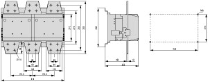
 106727 XTCEC16R22B EATON ELECTRIC Contactor, 3p+2N/O+2N/C, 1600A/AC1") View larger
View larger
 106727 XTCEC16R22B EATON ELECTRIC Contactor, 3p+2N/O+2N/C, 1600A/AC1")