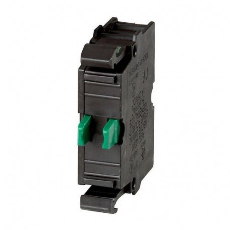
M22-CK10 216384 M22-CK10Q EATON ELECTRIC contato M22-CK10Q, fixação frontal Ver maior
As imagens são só a título ilustrativo. Por favor, consulte a ficha técnica.

M22-CK10 216384 M22-CK10Q EATON ELECTRIC contato M22-CK10Q, fixação frontal

M22-CK10

216384

M22-CK10Q

EATON-MOELLER

20

contato M22-CK10Q, fixação frontal

Elemento de contato 1 SEM conexão de montagem frontal para montagem frontal

Eaton Moeller® series M22 Contact element, Cage Clamp, Front fixing, 1 N/O, 24 V 3 A, 220 V 230 V 240 V 6 A

Mais detalhes


Disjuntores de baixa tensão > Bloco de contatos auxiliares

Auxiliares de controle e sinalização

* Produto novo em sua embalagem original com todas as garantias e certificações de EATON-MOELLER

Quantidade Preço
20+$5.29
40+$4.73
80+$4.31
120+$4.14
160+$4.06
*Este preço é por unidade e mostra o valor líquido (excluindo impostos indirectos se aplicável).

Se o nosso preço não é o melhor, peça-nos uma cotação Solicitar uma cotação

geralmente comprados juntos

Best sellers

Mais informação


General specifications

Product Name
Eaton Moeller® series M22 Accessory Contact element
Catalog Number
216384
EAN
4015082163846
Product Length/Depth
38 mm
Product Height
10 mm
Product Width
32 mm
Product Weight
0.01 kg
Compliances
CE Marked
Certifications
UL 508
CSA Std. C22.2 No. 94-91
CSA Std. C22.2 No. 14-05
EN 60947-5
IEC 60947-5
CE
CSA File No.: 012528
CSA-C22.2 No. 94-91
IEC 60947-5-1
UL
UL Category Control No.: NKCR
CSA Class No.: 3211-03
UL/CSA
UL File No.: E29184
CSA
IEC
IEC/EN 60947-5
CSA-C22.2 No. 14-05
Model Code
M22-CK10

Especificações do produto

Type
Auxiliary contact
10.10 Temperature rise
The panel builder is responsible for the temperature rise calculation. Eaton will provide heat dissipation data for the devices.
10.11 Short-circuit rating
Is the panel builder's responsibility. The specifications for the switchgear must be observed.
10.12 Electromagnetic compatibility
Is the panel builder's responsibility. The specifications for the switchgear must be observed.
10.13 Mechanical function
The device meets the requirements, provided the information in the instruction leaflet (IL) is observed.
10.2.2 Corrosion resistance
Meets the product standard's requirements.
10.2.3.1 Verification of thermal stability of enclosures
Meets the product standard's requirements.
10.2.3.2 Verification of resistance of insulating materials to normal heat
Meets the product standard's requirements.
10.2.3.3 Resist. of insul. mat. to abnormal heat/fire by internal elect. effects
Meets the product standard's requirements.
10.2.4 Resistance to ultra-violet (UV) radiation
Meets the product standard's requirements.
10.2.5 Lifting
Does not apply, since the entire switchgear needs to be evaluated.
10.2.6 Mechanical impact
Does not apply, since the entire switchgear needs to be evaluated.
10.2.7 Inscriptions
Meets the product standard's requirements.
10.3 Degree of protection of assemblies
Does not apply, since the entire switchgear needs to be evaluated.
10.4 Clearances and creepage distances
Meets the product standard's requirements.
10.5 Protection against electric shock
Does not apply, since the entire switchgear needs to be evaluated.
10.6 Incorporation of switching devices and components
Does not apply, since the entire switchgear needs to be evaluated.
10.7 Internal electrical circuits and connections
Is the panel builder's responsibility.
10.8 Connections for external conductors
Is the panel builder's responsibility.
10.9.2 Power-frequency electric strength
Is the panel builder's responsibility.
10.9.3 Impulse withstand voltage
Is the panel builder's responsibility.
10.9.4 Testing of enclosures made of insulating material
Is the panel builder's responsibility.
Electric connection type
Spring clamp connection
Operating frequency
3600 Operations/h
Pollution degree
3
Used with
Can be used with NZM1 circuit-breaker: a standard auxiliary contact can be clipped into the circuit-breaker.
Can be used with NZM2 size circuit-breaker: a standard auxiliary contact can be clipped into the circuit-breaker.
Can be used with NZM4 circuit-breaker: up to two standard auxiliary contacts can be clipped into the circuit-breaker.
Can be used with NZM1, 2, 3 circuit-breaker: a trip-indicating auxiliary contact can be clipped into the circuit-breaker.
Can be used with NZM3, 4 circuit-breaker: up to three standard auxiliary contacts can be clipped into the circuit-breaker.
Climatic proofing
Damp heat, cyclic, to IEC 60068-2-30
Damp heat, constant, to IEC 60068-2-78
Actuating force - max
5 N
Ambient operating temperature - max
70 °C
Ambient operating temperature - min
-25 °C
Conventional thermal current ith of auxiliary contacts (1-pole, open)
4 A
Equipment heat dissipation, current-dependent Pvid
0 W
Force for positive opening - min
0 N
Heat dissipation capacity Pdiss
0 W
Heat dissipation per pole, current-dependent Pvid
0.11 W
Number of contacts (change-over contacts)
0
Number of contacts (normally closed contacts)
0
Number of contacts (normally open contacts)
1
Number of switches (fault signal)
0
Connection to SmartWire-DT
No
Rated impulse withstand voltage (Uimp)
6000 V AC
Contact configuration
1 NO
Color
Green
Connection type
Front fixing
Single contact
Cage Clamp
Mounting method
Front fastening
Overvoltage category
III
Control circuit reliability
1 failure per 5,000,000 switching operations (statistically determined, at 5 V DC/1 mA)
1 failure per 10,000,000 switching operations (Statistically determined, at 24 V DC/5 mA)
Degree of protection
IP20
Model
Top mounting and integrable
Lamp holder
None
Terminal capacity (solid/flexible with ferrule)
1 x (0,75 - 2,5) mm²
2 x (0,5 - 0,75) mm²
Lifespan, electrical
1,600,000 Operations (at 230 V, 0.5 A)
700,000 Operations (at 230 V, AC-15, 3 A)
1,200,000 Operations (at 12 V, DC-13, 2.8 A)
1,000,000 Operations (at 230 V, AC-15, 1 A)
Terminal capacity (stranded)
0.5 - 2.5 mm²
Lifespan, mechanical
5,000,000 Operations
Short-circuit protection
PKZM0-10/FAZ-B6/1, Contacts, Max. short-circuit protective device, Fuseless
Static heat dissipation, non-current-dependent Pvs
0 W
Product category
Accessories
Rated operational current (Ie) at DC-13, 500 V
0.1 A
Short-circuit protection rating
Max. 10 A gG/gL, Fuse, Contacts
Max. 10 A gG/gL, Fuse, Auxiliary contacts
Rated insulation voltage (Ui)
500 V
Rated operational current (Ie) at AC-15, 115 V
6 A
Rated operational current (Ie) at AC-15, 220 V, 230 V, 240 V
6 A
Rated operational current (Ie) at AC-15, 380 V, 400 V, 415 V
4 A
Rated operational current (Ie) at AC-15, 500 V
2 A
Rated operational current (Ie) at DC-13, 110 V
0.8 A
Rated operational current (Ie) at DC-13, 220 V, 230 V
0.3 A
Rated operational current (Ie) at DC-13, 24 V
3 A
Rated operational current (Ie) at DC-13, 42 V
1.7 A
Rated operational current (Ie) at DC-13, 60 V
1.2 A
Rated operational current for specified heat dissipation (In)
6 A
Rated operational voltage (Ue) at AC - max
500 V
Rated operational voltage (Ue) at DC - max
220 V
Terminal capacity (flexible with ferrule)
0.5 - 1.5 mm²
Terminal capacity (solid)
0.75 - 2.5 mm²
Shock resistance
30 g, Mechanical, according to IEC/EN 60068-2-27, Shock duration 11 ms

Datasheet - PDF

Avaliações: (0)

Não há comentários do produto ainda.

Adicionar avaliação
ocultar formulário
Avaliação:
Nome:
Email:
Título:
Opinión:
  Captcha
  Adicionar avaliação

Todas as classificações que recebemos a partir dos itens que oferecemos são reais e verificadas. Um pequeno gesto, mas muito valioso. Então, obrigado por esse minuto você gasta em deixar-nos a sua opinião e classificação de produtos, porque nos ajuda a continuar a melhorar e oferecer maior qualidade de serviço.