
Ningún producto
Producto añadido correctamente a su carrito de la compra


 Ver más grande

A4EG-BE2R041 247805 OMRON Mando de validación con E-stop
A4EG-BE2R041
247805
OMRON
Mando de validación con E-stop
Productos de Seguridad > Otros Seguridad
* Producto nuevo en su embalaje original con todas las garantías y certificaciones de OMRON
Más Información
▲Módulo de seguridad de operación seleccionable G9SX-GS/A4EG
Controlador de seguridad que admite el modo de mantenimiento y el modo de funcionamiento normal.
- dos modos de funcionamiento: el modo de funcionamiento automático para aplicaciones donde la máquina y el operario cooperan y el modo manual para realizar labores de mantenimiento
- fácil diagnosis mediante LEDs de todas las entradas y salidas
- aplicable hasta categoría 4 según EN 954-1
Enabling grip switches
Safety guard switching units
Safety outputs1 | Auxiliary outputs2 | Max. OFF | ||||||
|---|---|---|---|---|---|---|---|---|
OFF-delayed4 | ||||||||
Specifications
Ratings of guard switching unit
Power input
Inputs
Operating voltage: 20.4 VDC to 26.4 VDC, internal impedance: approx. 2.8 kΩ | |
Outputs
Application example
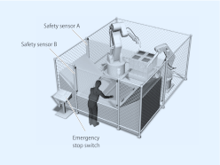
Automatic switching mode
Worker is loading and unloading the machine manually. When loading is finished, robot cycle is started manually by the worker. When robots return to their home position, loading cycle is selected automatically.
Loading condition: Safety sensor B is not active, safety sensor A is active because the robots are not allowed to move to the loading area while the worker loads the machine. So the worker is safe because safety sensor A is active.
Robot work condition: Safety sensor B is active, safety sensor A is not active because the worker is not allowed to move to the loading area when the robots work. So the worker is safe because safety sensor B stops the machine if he moves to the loading area.
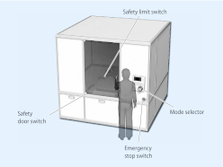
Manual switching mode
Worker has to do maintenance in this machine. While maintenance, it is necessary to move the machine in a limited way. The worker has to select automatic mode or manual mode manually by using the mode selector switch.
Operation steps:
1)Select maintenance mode by using the mode selector
2)Open the door to do the maintenance while the machine still is able to operate in a limited way (monitoring of limited movement by using the safety limit switch).
3)Close the cover after finishing maintenance
4)Select automatic mode by using the mode selector
E-Stop conditions:
a)open the door while not in maintenance mode
b)the machine actuates the limit switch (breaks the limit).
c)the Enabling grip switch A4EG is actuated to stop the machine in emergency condition.
Datasheet - PDF
▲| Título: | Tamaño: | Tipo: |
|---|---|---|
| A4EG-BE2R041 247805 | 240 Kbytes |
 |
| A4EG-BE2R041 247805 a4eg_datasheet_en.pdf | 3 Mbytes |
|
Opiniones: (0) ▲
Ningún comentario por el momento.
| Valoración: |
|
| Nombre: | |
| Email: | |
| Título: | |
| Opinión: | |
| ¿Recomienda la compra de este producto? | |
|
|
|
| Añadir comentario | |
Todas las valoraciones que recibimos de los artículos que ofrecemos son reales y están verificadas. Un pequeño gesto, pero de mucho valor. Por eso, te agradecemos ese minuto que inviertes en dejarnos tu opinión y calificación sobre los productos, porque nos ayuda a seguir mejorando y a ofrecerte un servicio de todavía mayor calidad.