
Нет товаров
Товар добавлен в корзину


 Увеличить

A4EG-BE2R041 247805 OMRON Security Products, валидация Команда E-стоп
A4EG-BE2R041
247805
OMRON
Security Products, валидация Команда E-стоп
Безопасность > Другие Безопасность
* Новый продукт в оригинальной упаковке со всеми гарантиями и сертификатами OMRON
Описание
▲переключающий модуль для защитных ограждений
Контроллер безопасности для реализации безопасного режима технического обслуживания и безопасного режима нормальной работы.
- два режима работы: автоматическое переключение в системах с одновременной работой машины и персонала и ручное переключение в системах с ограниченной работой, например, во время технического обслуживания
- наглядная светодиодная диагностика всех входов и выходов
- применимость для систем вплоть до категории 3 по EN 954-1
Enabling grip switches
Safety guard switching units
Safety outputs1 | Auxiliary outputs2 | Max. OFF | ||||||
|---|---|---|---|---|---|---|---|---|
OFF-delayed4 | ||||||||
Specifications
Ratings of guard switching unit
Power input
Inputs
Operating voltage: 20.4 VDC to 26.4 VDC, internal impedance: approx. 2.8 kΩ | |
Outputs
Application example
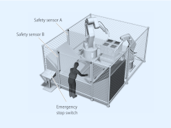
Automatic switching mode
Worker is loading and unloading the machine manually. When loading is finished, robot cycle is started manually by the worker. When robots return to their home position, loading cycle is selected automatically.
Loading condition: Safety sensor B is not active, safety sensor A is active because the robots are not allowed to move to the loading area while the worker loads the machine. So the worker is safe because safety sensor A is active.
Robot work condition: Safety sensor B is active, safety sensor A is not active because the worker is not allowed to move to the loading area when the robots work. So the worker is safe because safety sensor B stops the machine if he moves to the loading area.
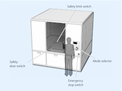
Manual switching mode
Worker has to do maintenance in this machine. While maintenance, it is necessary to move the machine in a limited way. The worker has to select automatic mode or manual mode manually by using the mode selector switch.
Operation steps:
1)Select maintenance mode by using the mode selector
2)Open the door to do the maintenance while the machine still is able to operate in a limited way (monitoring of limited movement by using the safety limit switch).
3)Close the cover after finishing maintenance
4)Select automatic mode by using the mode selector
E-Stop conditions:
a)open the door while not in maintenance mode
b)the machine actuates the limit switch (breaks the limit).
c)the Enabling grip switch A4EG is actuated to stop the machine in emergency condition.
Datasheet - PDF
▲| Заглавие: | Размер: | Тип: |
|---|---|---|
| A4EG-BE2R041 247805 | 240 Kbytes |
 |
| A4EG-BE2R041 247805 a4eg_datasheet_en.pdf | 3 Mbytes |
|
Отзывы: (0) ▲
Там нет Отзывы о товаре пока нет.
| Рейтинг: |
|
| Имя: | |
| Эл. адрес: | |
| Предмет: | |
| Текст: | |
| Вы рекомендуете этот продукт купить? | |
|
|
|
| Добавить отзыв | |
Все оценки, которые мы получаем о артикулах, которые мы предлагаем, являются реальными и проверенными. Маленький жест, но очень ценный. Вот почему мы благодарим Вас за ту минуту, которую Вы инвестируете в то, чтобы оставить нам свое мнение о продуктах, это помогает нам продолжать совершенствоваться и предлагать Вам услугу еще более высокого качества.