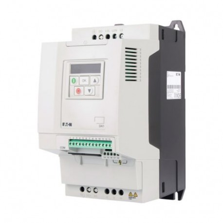
DA1-35012NB-A20C 177039 EATON ELECTRIC Convertitore di frequenza 3/3 600 V 12A 7,5 kW Controllo Vettoriale T.. Visualizza ingrandito
Le immagini sono solo per fini illustrativi. Si prega di fare riferimento alla scheda tecnica p...

DA1-35012NB-A20C 177039 EATON ELECTRIC Convertitore di frequenza 3/3 600 V 12A 7,5 kW Controllo Vettoriale T..

DA1-35012NB-A20C

177039

EATON-MOELLER

Convertitore di frequenza; 3/3; 600 V; 12A; 7,5 kW; Controllo Vettoriale; Transistor di Frenatura

Convertitore di frequenza ENT: 3 x 600 V Sale: 3 x 600 V 12A 7,5 kW

Eaton DA1 Variable frequency drive, 500 V AC, 3-phase, 12 A, 7.5 kW, IP20/NEMA 0, 7-digital display assembly

Maggiori dettagli


apparecchi elettrici a bassa tensione > convertitore di frequenza el 1 Kv

Convertitori di frequenza Power XL

* Prodotto nuovo nel suo imballaggio d'origine con tutte le garanzie e certificazioni de EATON-MOELLER

Prezzo totale: $1,287.75
Prezzo unitario: $1,287.75

*Questo prezzo è per unità e mostra il valore netto ( escluse le imposte indirette se applicabile ).

Se il nostro prezzo non è il migliore, chiedici un preventivo Richiedi un preventivo

Più venduti

Dettagli


General specifications

Product Name
Eaton DA1 Variable frequency drive
Catalog Number
177039
EAN
4015081714827
Product Length/Depth
204 mm
Product Height
273 mm
Product Width
131 mm
Product Weight
3.5 kg
Certifications
IEC/EN61800-5
RCM
UkrSEPRO
UL Category Control No.: NMMS, NMMS7
UL File No.: E172143
CSA-C22.2 No. 14
IEC/EN61800-3
Specification for general requirements: IEC/EN 61800-2
CE
Certified by UL for use in Canada
IEC/EN 61800-3
UL 508C
RoHS, ISO 9001
UL
Safety: EN 61800-5-1: 2003
CUL
UL report applies to both US and Canada
EAC
Catalog Notes
The brake resistors are assigned based on the maximum rated power of the variable frequency drive. Additional brake resistors and designs (e.g. different duty cycles) are available upon request.
Model Code
DA1-35012NB-A20C

General

Cable length
200 m, screened, with motor choke, maximum permissible, Motor feeder
100 m, screened, maximum permissible, Motor feeder
300 m, unscreened, with motor choke, maximum permissible, Motor feeder
150 m, unscreened, maximum permissible, Motor feeder
Communication interface
CANopen®, built in
PROFINET, optional
DeviceNet, optional
Modbus-TCP, optional
EtherCAT, optional
Modbus RTU, built in
PROFIBUS, optional
SmartWire-DT, optional
OP-Bus (RS485), built in
Ethernet IP, optional
Connection to SmartWire-DT
In conjunction with DX-NET-SWD1 SmartWire DT module
Yes
Degree of protection
IP20
NEMA Other
Fitted with:
Brake chopper
PC connection
IGBT inverter
7-digital display assembly
Breaking resistance
Internal DC link
Control unit
Additional PCB protection
Frame size
FS3
Functions
4-quadrant operation possible
Mounting position
Vertical
Product Category
Variable frequency drives
Protection
Finger and back-of-hand proof, Protection against direct contact (BGV A3, VBG4)
Protocol
EtherNet/IP
Other bus systems
PROFIBUS
DeviceNet
CAN
MODBUS
PROFINET IO
TCP/IP
Safety function/level
STO (Safe Torque Off, SIL2, PLc Cat 2)
Suitable for
Branch circuits, (UL/CSA)

Climatic environmental conditions

Ambient operating temperature - min
-10 °C
Altitude
Max. 4000 m
Max. 1000 m
Above 1000 m with 1 % derating per 100 m
Ambient operating temperature - max
50 °C
Ambient operating temperature at 150% overload - min
-10 °C
Ambient operating temperature at 150% overload - max
50 °C
Ambient storage temperature - min
-40 °C
Ambient storage temperature - max
60 °C
Climatic proofing
< 95 average relative humidity (RH), no condensation, no corrosion

Main circuit

Efficiency
97 % (η)
Heat dissipation at current/speed
129 W at 100% current and 0% speed
136 W at 100% current and 50% speed
163 W at 100% current and 90% speed
86 W at 25% current and 0% speed
86 W at 50% current and 0% speed
88 W at 25% current and 50% speed
88 W at 50% current and 50% speed
96 W at 50% current and 90% speed
Input current ILN at 150% overload
15.1 A
Leakage current at ground IPE - max
12 mA
Mains switch-on frequency
Maximum of one time every 30 seconds
Mains voltage - min
500 V
Mains voltage - max
600 V
Operating mode
U/f control
Optional: Vector control with feedback (CLV)
Sensorless vector control (SLV)
Speed control with slip compensation
Output frequency - min
0 Hz
Output frequency - max
500 Hz
Output voltage (U2)
600 V AC, 3-phase
500 V AC, 3-phase
Overload current IL at 150% overload
18 A
Rated control supply voltage
10 V DC (Us, max. 10 mA)
Rated frequency - min
48 Hz
Rated frequency - max
62 Hz
Rated operational current (Ie) at 150% overload
12 A
Rated operational power at 500 V, 50 Hz, 3-phase
7.5 kW
Rated operational power at 525 V, 50 Hz, 3-phase
7.5 kW
Rated operational voltage
500 V AC, 3-phase
600 V AC, 3-phase
Resolution
0.1 Hz (Frequency resolution, setpoint value)
Short-circuit protection
NH fuse used together with TB00-D fuse base, Power wiring, Assigned switching and protective elements
LPJ fuse used together with J60060-3 fuse base, Power wiring, Assigned switching and protective elements
Short-circuit protection rating
25 A, UL (Class CC or J), Safety device (fuse or miniature circuit-breaker), Power Wiring
Starting current - max
200 %, IH, max. starting current (High Overload), for 4 seconds every 40 seconds, Power section
Supply frequency
50/60 Hz
Switching frequency
8 kHz, 4 - 24 kHz adjustable (audible), fPWM, Power section, Main circuit
System configuration type
AC supply systems with earthed center point
Voltage rating - max
600 VAC

Motor rating

Assigned motor current IM at 500 V, 50 Hz, 150% overload
12 A
Assigned motor current IM at 525 V, 50 Hz, 150% overload
11.6 A
Assigned motor current IM at 550 - 600 V, 60 Hz, 150% overload
11 A
Assigned motor power at 575/600 V, 60 Hz, 3-phase
10 HP

Apparent power

Apparent power at 600 V
12.47 kVA

Braking function

Braking resistance
80 Ω
Braking torque
Max. 30 % MN, Standard - Main circuit
Max. 100 % of rated operational current Ie, variable, DC - Main circuit
Max. 100 % of rated operational current Ie with external braking resistor - Main circuit
Switch-on threshold for the braking transistor
975 VDC

Control circuit

Number of inputs (analog)
2
Number of inputs (digital)
5
Number of outputs (analog)
2
Number of outputs (digital)
2
Number of relay outputs
2 (parameterizable, 1 N/O and 1 changeover contact, 6 A (250 V, AC-1) / 5 A (30 V, DC-1))
Rated control voltage (Uc)
24 V DC (external, max. 100 mA)

Design verification

Equipment heat dissipation, current-dependent Pvid
225 W
Heat dissipation capacity Pdiss
0 W
Heat dissipation per pole, current-dependent Pvid
0 W
Rated operational current for specified heat dissipation (In)
12 A
Static heat dissipation, non-current-dependent Pvs
0 W
Heat dissipation details
Operation (with 150 % overload)
10.2.2 Corrosion resistance
Meets the product standard's requirements.
10.2.3.1 Verification of thermal stability of enclosures
Meets the product standard's requirements.
10.2.3.2 Verification of resistance of insulating materials to normal heat
Meets the product standard's requirements.
10.2.3.3 Resist. of insul. mat. to abnormal heat/fire by internal elect. effects
Meets the product standard's requirements.
10.2.4 Resistance to ultra-violet (UV) radiation
Meets the product standard's requirements.
10.2.5 Lifting
Does not apply, since the entire switchgear needs to be evaluated.
10.2.6 Mechanical impact
Does not apply, since the entire switchgear needs to be evaluated.
10.2.7 Inscriptions
Meets the product standard's requirements.
10.3 Degree of protection of assemblies
Does not apply, since the entire switchgear needs to be evaluated.
10.4 Clearances and creepage distances
Meets the product standard's requirements.
10.6 Incorporation of switching devices and components
Does not apply, since the entire switchgear needs to be evaluated.
10.7 Internal electrical circuits and connections
Is the panel builder's responsibility.
10.8 Connections for external conductors
Is the panel builder's responsibility.
10.9.2 Power-frequency electric strength
Is the panel builder's responsibility.
10.9.3 Impulse withstand voltage
Is the panel builder's responsibility.
10.9.4 Testing of enclosures made of insulating material
Is the panel builder's responsibility.
10.10 Temperature rise
The panel builder is responsible for the temperature rise calculation. Eaton will provide heat dissipation data for the devices.
10.11 Short-circuit rating
Is the panel builder's responsibility. The specifications for the switchgear must be observed.
10.12 Electromagnetic compatibility
Is the panel builder's responsibility. The specifications for the switchgear must be observed.
10.13 Mechanical function
The device meets the requirements, provided the information in the instruction leaflet (IL) is observed.

Datasheet - PDF

Recensioni: (0)

Nessun commento per il momento.

Inserisci recensione
nascondi form
Valutazione:
Nome:
Email:
Titolo:
Testo:
  Captcha
  Inserisci recensione

Tutti i feedback che riceviamo dagli elementi che offriamo sono reali e verificati. Un piccolo gesto, ma di grande valore. Quindi grazie per quel minuto si spende in noi lasciare il vostro parere e punteggio sui prodotti, perché ci aiuta a continuare a migliorare e di offrire ancora maggiore qualità del servizio.