ANUNCIAR
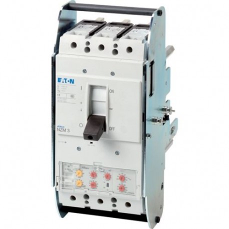
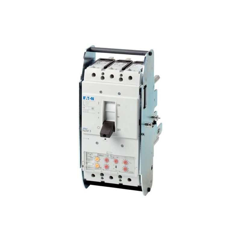
NZMN3-VE250-T-AVE 113529 Y7-113529 EATON ELECTRIC Interruttore automatico di potenza, 3p, 250A, cassetto Visualizza ingrandito
Le immagini sono solo per fini illustrativi. Si prega di fare riferimento alla scheda tecnica p...

NZMN3-VE250-T-AVE 113529 Y7-113529 EATON ELECTRIC Interruttore automatico di potenza, 3p, 250A, cassetto

NZMN3-VE250-T-AVE

113529

Y7-113529

EATON-MOELLER

Interruttore automatico di potenza, 3p, 250A, cassetto

Automatico Int. NZM, 3P, 250A, Rimovibile

Eaton Moeller series NZM - Molded Case Circuit Breaker. Circuit-breaker, 3p, 250A, withdrawable unit, NZMN3-VE250-T-AVE

Interruttore automatico NZM3, 3 poli, Potenza di commutazione 400/415 V 50 Hz( Icu ): 50 kA, Corrente nominale = corrente nominale ininterrotta Corrente nominale = Corrente nominale ininterrotta ( In = Iu ): 250 A, Tipo di installazione: Rimovibile, Collegamento a vite, Standard/Approvazione: IEC, Funzione di protezione: Sistemi, cavo, selettività e protezione del generatore

Maggiori dettagli


Apparecchi elettrici a bassa tensione > Breaker per trasformatori / generatori / impianti

Interruttori automatici con custodia modellata NZM

Prodotto nuovo nel suo imballaggio d'origine con tutte le garanzie e certificazioni de EATON-MOELLER

Prezzo totale: $3,728.84
Prezzo unitario: $3,728.84
Questo prezzo è per unità e mostra il valore netto ( escluse le imposte indirette se applicabile ).

Se il nostro prezzo non è il migliore, chiedici un preventivo Richiedi un preventivo

Related products

Più venduti

Dettagli


General specifications

Product Name
Eaton Moeller series NZM molded case circuit breaker electronic
Catalog Number
113529
EAN
4015081130542
Product Length/Depth
346 mm
Product Height
260 mm
Product Width
185 mm
Product Weight
11.129 kg
Compliances
RoHS conform
Certifications
IEC/EN 60947
IEC
Model Code
NZMN3-VE250-T-AVE

Specifiche del prodotto

Type
Circuit breaker
Special features
Application
Use in unearthed supply systems at 690 V
Amperage Rating
250 A
Voltage rating
690 V - 690 V
Circuit breaker frame type
NZM3
Features
Protection unit
Motor drive optional
Accessories required
NZM3-XAVS
10.10 Temperature rise
The panel builder is responsible for the temperature rise calculation. Eaton will provide heat dissipation data for the devices.
10.11 Short-circuit rating
Is the panel builder's responsibility. The specifications for the switchgear must be observed.
10.12 Electromagnetic compatibility
Is the panel builder's responsibility. The specifications for the switchgear must be observed.
10.13 Mechanical function
The device meets the requirements, provided the information in the instruction leaflet (IL) is observed.
10.2.2 Corrosion resistance
Meets the product standard's requirements.
10.2.3.1 Verification of thermal stability of enclosures
Meets the product standard's requirements.
10.2.3.2 Verification of resistance of insulating materials to normal heat
Meets the product standard's requirements.
10.2.3.3 Resist. of insul. mat. to abnormal heat/fire by internal elect. effects
Meets the product standard's requirements.
10.2.4 Resistance to ultra-violet (UV) radiation
Meets the product standard's requirements.
10.2.5 Lifting
Does not apply, since the entire switchgear needs to be evaluated.
10.2.6 Mechanical impact
Does not apply, since the entire switchgear needs to be evaluated.
10.2.7 Inscriptions
Meets the product standard's requirements.
10.3 Degree of protection of assemblies
Does not apply, since the entire switchgear needs to be evaluated.
10.4 Clearances and creepage distances
Meets the product standard's requirements.
10.5 Protection against electric shock
Does not apply, since the entire switchgear needs to be evaluated.
10.6 Incorporation of switching devices and components
Does not apply, since the entire switchgear needs to be evaluated.
10.7 Internal electrical circuits and connections
Is the panel builder's responsibility.
10.8 Connections for external conductors
Is the panel builder's responsibility.
10.9.2 Power-frequency electric strength
Is the panel builder's responsibility.
10.9.3 Impulse withstand voltage
Is the panel builder's responsibility.
10.9.4 Testing of enclosures made of insulating material
Is the panel builder's responsibility.
Pollution degree
3
Mounting Method
Built-in device slide-in technique (withdrawable)
Withdrawable
Climatic proofing
Damp heat, cyclic, to IEC 60068-2-30
Damp heat, constant, to IEC 60068-2-78
Equipment heat dissipation, current-dependent
18.75 W
Utilization category
A (IEC/EN 60947-2)
Isolation
300 V AC (between the auxiliary contacts)
500 V AC (between auxiliary contacts and main contacts)
Ambient operating temperature - max
70 °C
Ambient operating temperature - min
-25 °C
Ambient storage temperature - max
70 °C
Ambient storage temperature - min
40 °C
Number of auxiliary contacts (change-over contacts)
0
Number of auxiliary contacts (normally closed contacts)
0
Number of auxiliary contacts (normally open contacts)
0
Protection against direct contact
Finger and back-of-hand proof to DIN EN 50274/VDE 0106 part 110
Degree of protection
IP20 (basic degree of protection, in the operating controls area)
IP20
Direction of incoming supply
As required
Electrical connection type of main circuit
Screw connection
Lifespan, mechanical
15000 operations
Overvoltage category
III
Degree of protection (IP), front side
IP40 (with insulating surround)
IP66 (with door coupling rotary handle)
Degree of protection (terminations)
IP10 (tunnel terminal)
IP00 (terminations, phase isolator and strip terminal)
Number of poles
Three-pole
Terminal capacity (copper strip)
Min. 6 segments of 16 mm x 0.8 mm at box terminal
10 segments of 50 mm x 1 mm (2x) at rear-side width extension
Max. 8 segments of 24 mm x 1 mm (2x) at box terminal
Max. 10 segments of 24 mm x 1 mm + 5 segments of 24 mm x 1 mm
Max. 10 segments of 32 mm x 1 mm + 5 segments of 32 mm x 1 mm at rear-side connection (punched)
Min. 6 segments of 16 mm x 0.8 mm at rear-side connection (punched)
Lifespan, electrical
3000 operations at 690 V AC-1
2000 operations at 400 V AC-3
5000 operations at 415 V AC-1
2000 operations at 690 V AC-3
5000 operations at 400 V AC-1
2000 operations at 415 V AC-3
Functions
Integrated earth fault protection
Earth-fault protection
Systems, cable, selectivity and generator protection
Shock resistance
20 g (half-sinusoidal shock 20 ms)
Position of connection for main current circuit
Front side
Rated operational current for specified heat dissipation (In)
250 A
Release system
Electronic release
Short-circuit total breaktime
< 10 ms
Rated short-time withstand current (t = 0.3 s)
3.3 kA
Rated short-time withstand current (t = 1 s)
3.3 kA
Short-circuit release delayed setting - max
2500 A
Short-circuit release delayed setting - min
250 A
Short-circuit release non-delayed setting - max
2750 A
Short-circuit release non-delayed setting - min
500 A
Terminal capacity (control cable)
0.75 mm² - 2.5 mm² (1x)
0.75 mm² - 1.5 mm² (2x)
Terminal capacity (copper busbar)
M10 at rear-side screw connection
Max. 30 mm x 10 mm + 30 mm x 5 mm direct at switch rear-side connection
Min. 20 mm x 5 mm direct at switch rear-side connection
Max. 10 mm x 50 mm (2x) at rear-side width extension
Terminal capacity (copper solid conductor/cable)
300 mm² (2x) at rear-side width extension
16 mm² (2x) at box terminal
16 mm² (2x) direct at switch rear-side connection
16 mm² (1x) direct at switch rear-side connection
16 mm² (1x) at tunnel terminal
Terminal capacity (aluminum solid conductor/cable)
16 mm² (1x) at tunnel terminal
Terminal capacity (copper stranded conductor/cable)
35 mm² - 240 mm² (1x) at box terminal
25 mm² - 240 mm² (1x) direct at switch rear-side connection
25 mm² - 240 mm² (2x) direct at switch rear-side connection
16 mm² - 185 mm² (1x) at 1-hole tunnel terminal
25 mm² - 120 mm² (2x) at box terminal
Terminal capacity (aluminum stranded conductor/cable)
50 mm² - 240 mm² (1x) at 2-hole tunnel terminal
50 mm² - 240 mm² (2x) at 2-hole tunnel terminal
25 mm² - 185 mm² (1x) at tunnel terminal
Handle type
Rocker lever
Short delay current setting (Isd) - max
2500 A
Short delay current setting (Isd) - min
250 A
Instantaneous current setting (Ii) - max
2750 A
Instantaneous current setting (Ii) - min
500 A
Number of operations per hour - max
60
Overload current setting (Ir) - max
250 A
Overload current setting (Ir) - min
125 A
Rated short-circuit breaking capacity Ics (IEC/EN 60947) at 230 V, 50/60 Hz
85 kA
Rated short-circuit breaking capacity Ics (IEC/EN 60947) at 400/415 V, 50/60 Hz
50 kA
Rated short-circuit breaking capacity Ics (IEC/EN 60947) at 440 V, 50/60 Hz
35 kA
Rated short-circuit breaking capacity Ics (IEC/EN 60947) at 525 V, 50/60 Hz
13 kA
Rated short-circuit breaking capacity Ics (IEC/EN 60947) at 690 V, 50/60 Hz
5 kA
Rated short-circuit making capacity Icm at 400/415 V, 50/60 Hz
105 kA
Rated short-circuit making capacity Icm at 440 V, 50/60 Hz
74 kA
Rated short-circuit making capacity Icm at 525 V, 50/60 Hz
53 kA
Rated short-circuit making capacity Icm at 690 V, 50/60 Hz
40 kA
Standard terminals
Screw terminal
Optional terminals
Box terminal. Connection on rear. Tunnel terminal
Rated short-circuit making capacity Icm at 240 V, 50/60 Hz
187 kA
Rated impulse withstand voltage (Uimp) at auxiliary contacts
6000 V
Rated impulse withstand voltage (Uimp) at main contacts
8000 V
Rated insulation voltage (Ui)
1000 V AC

ETIM for 113529 Apparecchi elettrici a bassa tensione (EC000228)
Caratteristica Valore
corrente permanente nominale Iu (EF001389) 250 A
tensione nominale (EF003977) 690 V
corrente limite nominale di disinserzione al corto circuito a 400 V, 50 Hz (EF007048) 50 kA
campo di corrente dell'interruttore di sovraccarico (EF002336) 125 A
intervallo di regolazione dell'attivatore di corto circuito con ritardo breve (EF007129) 250 A
intervallo di regolazione dell'attivatore di corto circuito non ritardato (EF007131) 500 A
potenza dissipata (EF005387) None W
tipologia costruttiva dell'apparecchio (EF008240) Built-in device slide-in technique (withdrawable)
protezione dalle dispersioni a terra integrata (EF007296) true
tipo di collegamento circuito elettrico principale (EF006819) Screw connection
adatto per montaggio su guida a cappello (EF007250) false

montaggio su guida a DIN opzionale (EF008904) false
numero di contatti ausiliari, contatti di riposo (EF001377) 0
numero di contatti ausiliari, contatti di chiusura (EF001376) 0
numero di contatti ausiliari, invertitori (EF003531) 0
con segnalatore di intervento presente (EF007006) false
con sganciatore di minima tensione integrato (EF001390) false
numero di poli (EF001391) 3
posizione del collegamento per circuito elettrico principale (EF006671) Front side
tipo di elemento di azionamento (EF006976) Rocker lever
apparecchio completo con unità di sicurezza (EF008906) true
azionamento a motore integrato (EF006697) false
azionamento a motore opzionale (EF007386) true
grado di protezione (IP) (EF005474) IP20

Datasheet - PDF

Recensioni: (0)

Nessun commento per il momento.

Inserisci recensione
nascondi form
Valutazione:
Nome:
Email:
Titolo:
Testo:
  Captcha
  Inserisci recensione

Tutti i feedback che riceviamo dagli elementi che offriamo sono reali e verificati. Un piccolo gesto, ma di grande valore. Quindi grazie per quel minuto si spende in noi lasciare il vostro parere e punteggio sui prodotti, perché ci aiuta a continuare a migliorare e di offrire ancora maggiore qualità del servizio.