10.10 Temperature rise
The panel builder is responsible for the temperature rise calculation. Eaton will provide heat dissipation data for the devices.
10.11 Short-circuit rating
Is the panel builder's responsibility. The specifications for the switchgear must be observed.
10.12 Electromagnetic compatibility
Is the panel builder's responsibility. The specifications for the switchgear must be observed.
10.13 Mechanical function
The device meets the requirements, provided the information in the instruction leaflet (IL) is observed.
10.2.2 Corrosion resistance
Meets the product standard's requirements.
10.2.3.1 Verification of thermal stability of enclosures
Meets the product standard's requirements.
10.2.3.2 Verification of resistance of insulating materials to normal heat
Meets the product standard's requirements.
10.2.3.3 Resist. of insul. mat. to abnormal heat/fire by internal elect. effects
Meets the product standard's requirements.
10.2.4 Resistance to ultra-violet (UV) radiation
Meets the product standard's requirements.
10.2.5 Lifting
Does not apply, since the entire switchgear needs to be evaluated.
10.2.6 Mechanical impact
Does not apply, since the entire switchgear needs to be evaluated.
10.2.7 Inscriptions
Meets the product standard's requirements.
10.3 Degree of protection of assemblies
Does not apply, since the entire switchgear needs to be evaluated.
10.4 Clearances and creepage distances
Meets the product standard's requirements.
10.5 Protection against electric shock
Does not apply, since the entire switchgear needs to be evaluated.
10.6 Incorporation of switching devices and components
Does not apply, since the entire switchgear needs to be evaluated.
10.7 Internal electrical circuits and connections
Is the panel builder's responsibility.
10.8 Connections for external conductors
Is the panel builder's responsibility.
10.9.2 Power-frequency electric strength
Is the panel builder's responsibility.
10.9.3 Impulse withstand voltage
Is the panel builder's responsibility.
10.9.4 Testing of enclosures made of insulating material
Is the panel builder's responsibility.
Ambient operating temperature - max
Ambient operating temperature - min
Ambient operating temperature (enclosed) - max
Ambient operating temperature (enclosed) - min
Equipment heat dissipation, current-dependent Pvid
Heat dissipation capacity Pdiss
Heat dissipation per pole, current-dependent Pvid
Number of auxiliary contacts (normally closed contacts)
Number of auxiliary contacts (normally open contacts)
Number of contacts (normally closed) as main contact
Number of main contacts (normally open contact)
Rated control supply voltage (Us) at AC, 50 Hz - max
Rated control supply voltage (Us) at AC, 50 Hz - min
Rated control supply voltage (Us) at AC, 60 Hz - max
Rated control supply voltage (Us) at AC, 60 Hz - min
Rated control supply voltage (Us) at DC - max
Rated control supply voltage (Us) at DC - min
Rated operational current for specified heat dissipation (In)
Static heat dissipation, non-current-dependent Pvs
Switching time (AC operated, make contacts, closing delay) - min
Application
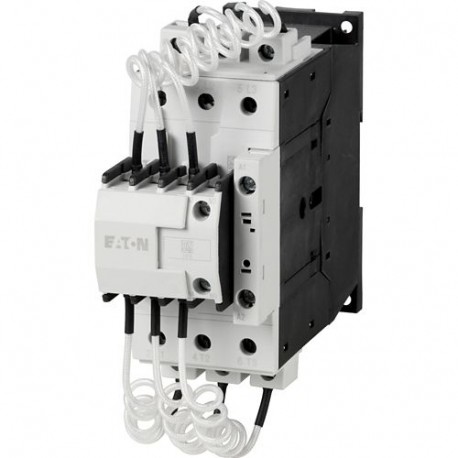
Contactors for power factor correction
Product category
DILK Contactors for capacitors
Protection
Finger and back-of-hand proof, Protection against direct contact when actuated from front (EN 50274)
Number of auxiliary contacts (change-over contacts)
Operating voltage at AC, 50 Hz - min
Operating voltage at AC, 50 Hz - max
Operating voltage at AC, 60 Hz - min
Operating voltage at AC, 60 Hz - max
Rated blind power at 400 V, 60 Hz
Electrical connection type of main circuit
Drop-out voltage
AC operated: 0.6 - 0.3 x UC, AC operated
Making capacity without damping (I-peak value)
Power consumption, pick-up, 50 Hz
45 VA, Dual-frequency coil in a cold state and 1.0 x Us, at 50 Hz
Power consumption, pick-up, 60 Hz
45 VA, Dual-frequency coil in a cold state and 1.0 x Us, at 60 Hz
Power consumption, sealing, 50 Hz
1.5 VA, Dual-frequency coil in a cold state and 1.0 x Us, at 50 Hz
4.1 W, Dual-frequency coil in a cold state and 1.0 x Us, at 50 Hz
Power consumption, sealing, 60 Hz
4.1 W, Dual-frequency coil in a cold state and 1.0 x Us, at 60 Hz
1.5 VA, Dual-frequency coil in a cold state and 1.0 x Us, at 60 Hz
Rated operational current (Ie)
45 A at 400 V (three-phase capacitors, enclosed)
50 A at 525 V (three-phase capacitors, open)
50 A at 690 V (three-phase capacitors, open)
45 A at 230 V (three-phase capacitors, enclosed)
50 A at 400 V (three-phase capacitors, open)
45 A at 690 V (three-phase capacitors, enclosed)
45 A at 525 V (three-phase capacitors, enclosed)
50 A at 230 V (three-phase capacitors, open)
Special purpose rating of capacitor switching
20 kVar, 240 V 60 Hz 3phase, (UL/CSA)
48 A, 480 V 60 Hz 3phase, (UL/CSA)
48 A, 240 V 60 Hz 3phase, (UL/CSA)
50 kVar, 600 V 60 Hz 3phase, (UL/CSA)
48 A, 600 V 60 Hz 3phase, (UL/CSA)
40 kVar, 480 V 60 Hz 3phase, (UL/CSA)
Terminal capacity (stranded)
1 x (16 - 50) mm², Main cables
Switching capacity (auxiliary contacts, general use)
1 A, 250 V DC, (UL/CSA)
10 A, 600 V AC, (UL/CSA)
Switching capacity (auxiliary contacts, pilot duty)
P300, DC operated (UL/CSA)
A600, AC operated (UL/CSA)
Terminal capacity (copper band)
1 x (6 x 9 x 0.8) mm (Number of segments x width x thickness), Main cables
Terminal capacity (flexible with ferrule)
1 x (2.5 - 35) mm², Main cables
Terminal capacity (solid)
1 x (2.5 - 16) mm², Main cables
Terminal capacity (solid/stranded AWG)
 Ver más grande


