M22-K01PV6 150643 M22-K01PV6Q EATON ELECTRIC Contact element 1N/C, front mount, screw connection, max. 6 for.. View larger
Images are for illustrative purposes only. Please refer to data sheet for details.

M22-K01PV6 150643 M22-K01PV6Q EATON ELECTRIC Contact element 1N/C, front mount, screw connection, max. 6 for..

M22-K01PV6

150643

M22-K01PV6Q

EATON-MOELLER

20

Contact element 1N/C, front mount, screw connection, max. 6 for emergency stop

M22-K01PV6

Contact element, Screw terminals, Front fixing, 1 NC, 24 V 3 A, only in connection with M22-PV… max. 6 contact elements M22-K01PV6

More details


Low-voltage industrial components > Auxiliary contact block

Auxiliary Control and Signalling Elements

* Brand new product in its original packaging covered by the warranties and certifications provided by EATON-MOELLER

Quantity Price
20+$5.82
40+$5.14
60+$4.86
80+$4.70
100+$4.65
*This price is per unit and is the net value (not including taxes if applicable).

If our price is not the best, please ask us for a quote. Ask for a quotation

More info


Contact element, Screw terminals, Front fixing, 1 NC, 24 V 3 A, only in connection with M22-PV… max. 6 contact elements M22-K01PV6
Contact element, Connection technique: Screw terminals, Fixing: Front fixing, Description: only in connection with M22-PV… max. 6 contact elements M22-K01PV6, Contacts N/C = Normally closed: 1 NC, Contacts Notes: = safety function, by positive opening to IEC/EN 60947-5-1, Actuator travel and actuation force as per DIN EN 60947-5-1, K.5.4.1: mm 4.8, Maximum travel: mm 5.7, Minimum force for positive opening: N 15, Degree of Protection: IP20, Connection to SmartWire-DT: no, Connection type: Single contact, Standards: IEC 60947-5-1

Delivery program

Basic function accessories
Contact elements
Description
only in connection with M22-PV… max. 6 contact elements M22-K01PV6
Connection technique
Screw terminals
Fixing
Front fixing
Degree of Protection
IP20
Connection to SmartWire-DT
no
Approval
000Z425
Contacts
N/C = Normally closed
1 NC
Notes
= safety function, by positive opening to IEC/EN 60947-5-1
Actuator travel and actuation force as per DIN EN 60947-5-1, K.5.4.1
[mm]
4.8
Maximum travel [mm]
5.7
Minimum force for positive opening [ N]
15
Contact sequence
116S041
Contact travel diagram, stroke in connection with front element
Contact diagram
116U023
Configuration
116Q003
Connection type
Single contact
Connection technique
Screw terminals

Technical data

General
Standards
IEC 60947-5-1
Actuating force
≦ 4 n
Operating torque (screw terminals)
≦ 0.8 Nm
Degree of Protection
IP20
Climatic proofing
Damp heat, constant, to IEC 60068-2-78
Damp heat, cyclic, to IEC 60068-2-30
Ambient temperatureOpen
-25 - +70 °C
Mechanical shock resistance to IEC 60068-2-27 Shock duration 11 ms, half-sinusoidal
> 30 g
Terminal capacitiesSolid
0.75 - 2.5 mm2
Terminal capacitiesStranded
0.5 - 2.5 mm2
Terminal capacitiesFlexible with ferrule
0.5 - 1.5 mm2
Contacts
Rated impulse withstand voltage [Uimp]
6000 V AC
Rated insulation voltage [Ui]
500 V
Overvoltage category/pollution degree
III/3
Control circuit reliabilityat 24 V DC/5 mA [HF]
< 10-7(i.e. 1 failure to 107operations) Fault probability
Control circuit reliabilityat 5 V DC/1 mA [HF]
< 5 x 10⁻⁶(i.e. 1 failure in 5 x 10⁶operations) Fault probability
Max. short-circuit protective deviceFuseless
PKZM0-10/FAZ-B6/1 Type
Max. short-circuit protective deviceFuse [gG/gL]
10 A
Switching capacity
Rated operational current [Ie]AC-15115 V [Ie]
6 A
Rated operational current [Ie]AC-15220 V 230 V 240 V [Ie]
6 A
Rated operational current [Ie]AC-15380 V 400 V 415 V [Ie]
4 A
Rated operational current [Ie]AC-15500 V [Ie]
2 A
Rated operational current [Ie]DC-1324 V [Ie]
3 A
Rated operational current [Ie]DC-1342 V [Ie]
1.7 A
Rated operational current [Ie]DC-13110 V [Ie]
0.6 A
Rated operational current [Ie]DC-13220 V [Ie]
0.3 A
Lifespan, electricalAC-15230 V/0.5 A [Operations]
1.6 x 10⁶
Lifespan, electricalAC-15230 V/1.0 A [Operations]
1 x 10⁶
Lifespan, electricalAC-15230 V/3.0 A [Operations]
0.7 x 10⁶
Lifespan, electricalDV-1312 V/2.8 A [Operations]
1.2 x 10⁶
Auxiliary contacts
Rated conditional short-circuit current [Iq]
1 kA
UL/CSARated operational current [Ie]
5 A – 600 V AC
1 A - 250 V DC A

Design verification as per IEC/EN 61439

Technical data for design verification
Rated operational current for specified heat dissipation [In]
6 A
Heat dissipation per pole, current-dependent [Pvid]
0.11 W
Equipment heat dissipation, current-dependent [Pvid]
0 W
Static heat dissipation, non-current-dependent [Pvs]
0 W
Heat dissipation capacity [Pdiss]
0 W
Operating ambient temperature min.
-25 °C
Operating ambient temperature max.
+70 °C
IEC/EN 61439 design verification
10.2 Strength of materials and parts10.2.2 Corrosion resistance
Meets the product standard's requirements.
10.2 Strength of materials and parts10.2.3.1 Verification of thermal stability of enclosures
Meets the product standard's requirements.
10.2 Strength of materials and parts10.2.3.2 Verification of resistance of insulating materials to normal heat
Meets the product standard's requirements.
10.2 Strength of materials and parts10.2.3.3 Verification of resistance of insulating materials to abnormal heat and fire due to internal electric effects
Meets the product standard's requirements.
10.2 Strength of materials and parts10.2.4 Resistance to ultra-violet (UV) radiation
Meets the product standard's requirements.
10.2 Strength of materials and parts10.2.5 Lifting
Does not apply, since the entire switchgear needs to be evaluated.
10.2 Strength of materials and parts10.2.6 Mechanical impact
Does not apply, since the entire switchgear needs to be evaluated.
10.2 Strength of materials and parts10.2.7 Inscriptions
Meets the product standard's requirements.
10.3 Degree of protection of ASSEMBLIES
Does not apply, since the entire switchgear needs to be evaluated.
10.4 Clearances and creepage distances
Meets the product standard's requirements.
10.5 Protection against electric shock
Does not apply, since the entire switchgear needs to be evaluated.
10.6 Incorporation of switching devices and components
Does not apply, since the entire switchgear needs to be evaluated.
10.7 Internal electrical circuits and connections
Is the panel builder's responsibility.
10.8 Connections for external conductors
Is the panel builder's responsibility.
10.9 Insulation properties10.9.2 Power-frequency electric strength
Is the panel builder's responsibility.
10.9 Insulation properties10.9.3 Impulse withstand voltage
Is the panel builder's responsibility.
10.9 Insulation properties10.9.4 Testing of enclosures made of insulating material
Is the panel builder's responsibility.
10.10 Temperature rise
The panel builder is responsible for the temperature rise calculation. Eaton will provide heat dissipation data for the devices.
10.11 Short-circuit rating
Is the panel builder's responsibility. The specifications for the switchgear must be observed.
10.12 Electromagnetic compatibility
Is the panel builder's responsibility. The specifications for the switchgear must be observed.
10.13 Mechanical function
The device meets the requirements, provided the information in the instruction leaflet (IL) is observed.

Technical data ETIM 7.0
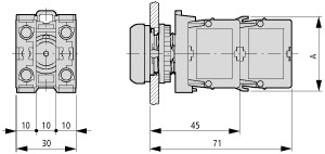
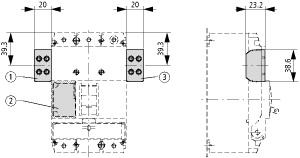
Low-voltage industrial components (EG000017) / Auxiliary contact block (EC000041)
Electric engineering, automation, process control engineering / Low-voltage switch technology / Component for low-voltage switching technology / Auxiliary switch block ([email protected] [AKN342013])
Number of contacts as change-over contact
0
Number of contacts as normally open contact
0
Number of contacts as normally closed contact
1
Number of fault-signal switches
0
Rated operation current Ie at AC-15, 230 V
6 A
Type of electric connection
Screw connection
Model
Top mounting
Mounting method
Front fastening
Lamp holder
None

Dimensions

116X101
A = 37.2
123X305

Datasheet - PDF

Reviews (0)

No customer reviews for the moment.

Add Review
hide form
Rating:
Name:
Email:
Subject:
Text:
  Captcha
  Add review

All ratings we receive from the items we offer are real and verified. A small gesture, but a lot of value. That's why we thank you for that minute you invest in leaving us your opinion and qualification about the products, because it helps us to continue improving and to offer you a service of even higher quality.