
5/5 .
— CHE 5/6/26, 10:33 AM
Customer rating:
Product:MTZ18-4VM DANFOSS REFRIGERATION Reciproc...
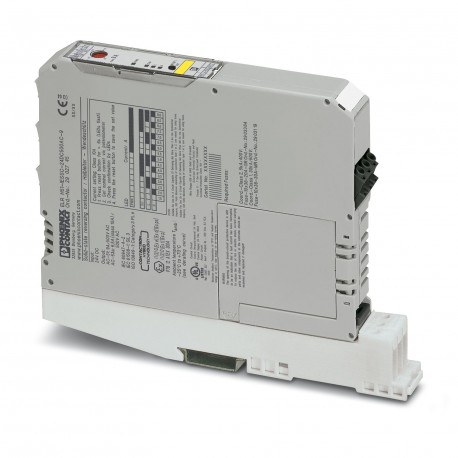
Images are for illustrative purposes only. Please refer to data sheet for details.
Reference: ELR H51-9-DIN-RAIL-SET
Code: 2902954
Manufacturer: PHOENIX CONTACT
Description:
Categories:
Brand new product in its original packaging covered by the warranties and certifications provided by PHOENIX CONTACT
* This article may be obsolete. Ask for a quotation and we will check if there are any units available. If not, one of our technicians will look for an alternative solution.
Ask for a quotation and we will check if there are any units available. If not, one of our technicians will look for an alternative solution.
LAST VIEWED
| Product type | Hybrid motor starters |
| Product family | CONTACTRON |
| Operating mode | 100% operating factor |
| Data management status | |
| Article revision | 04 |
| Number of phases | 3 |
| Motor starter type | Reversing starter |
| Switching frequency | ≤ 2 Hz (Load-dependent) |
| Maximum power dissipation for nominal condition | 11 W |
| Switching frequency | ≤ 2 Hz (Load-dependent) |
| Maximum power dissipation | 7 W |
| Minimum power dissipation | 0.88 W |
| Coordination type | 2 |
| Supply | |
| Rated control circuit supply voltage US | 24 V DC |
| Control supply voltage range | 19.2 V DC ... 30 V DC |
| Rated control supply current IS | 40 mA |
| Protective circuit | Surge protection |
| Reverse polarity protection; Parallel polarity protection diode | |
| Insulation characteristics | |
| Rated insulation voltage | 500 V |
| Rated surge voltage | 6 kV |
| Overvoltage category | III |
| Degree of pollution | 2 |
| Insulation characteristics between the control input and control supply voltage, and auxiliary circuit to the main circuit | Safe isolation (IEC 60947-1) at operating voltage ≤ 300 V AC |
| Safe isolation (EN 50178) at operating voltage ≤ 300 V AC | |
| Basic insulation (IEC 60947-1) at operating voltage 300 V AC ... 500 V AC | |
| Safe isolation (EN 50178) at operating voltage 300 ... 500 V AC | |
| Isolation characteristics between the control input and control supply voltage to auxiliary circuit | Safe isolation (IEC 60947-1) in the auxiliary circuit ≤ 300 V AC |
| Safe isolation (EN 50178) in the auxiliary circuit ≤ 300 V AC | |
| Emergency tripping | |
| Operate threshold | > 45 A |
| Response time | < 2 s |
| Control | |
| Input name | Control input right/left |
| Rated actuating voltage UC | 24 V DC |
| Triggering voltage range | 19.2 V DC ... 30 V DC |
| Rated actuating current IC | 5 mA |
| Switching threshold | 9.6 V (“0” signal) |
| 19.2 V (“1” signal) | |
| Switching level | < 5 V DC (For EMERGENCY STOP) |
| Typical turn-off time | < 30 ms |
| AC output | |
| Rated operating voltage Ue | 500 V AC |
| Operating voltage range | 42 V AC ... 550 V AC |
| Mains frequency | 50/60 Hz |
| Load current range | 1.5 A ... 9 A (see to derating) |
| Trigger characteristic in acc. with IEC 60947-4-2 | Class 10A |
| Cooling time | 20 min. (for auto reset) |
| Leakage current | 0 mA |
| Protective circuit | Surge protection; Varistor |
| Short-circuit protection; Fuse | |
| Acknowledge output | |
| Note | Confirmation: floating change-over contact, signal contact |
| Contact switching type | 1 changeover contact |
| Switching capacity in accordance with IEC 60947-5-1 | 3 A (230 V, AC15) |
| 2 A (24 V, DC13) | |
| Control circuits | |
| Connection method | Screw connection |
| Stripping length | 8 mm |
| Screw thread | M3 |
| Conductor cross section rigid | 0.2 mm² ... 2.5 mm² |
| Conductor cross section flexible | 0.2 mm² ... 2.5 mm² |
| Conductor cross section AWG | 24 ... 14 |
| Tightening torque | 0.5 Nm ... 0.6 Nm |
| 5 lbf-in. ... 7 lbf-in. | |
| Load circuit | |
| Connection method | Screw connection |
| Stripping length | 8 mm |
| Screw thread | M3 |
| Conductor cross section rigid | 0.2 mm² ... 2.5 mm² |
| Conductor cross section flexible | 0.2 mm² ... 2.5 mm² |
| Conductor cross section AWG | 24 ... 14 |
| Tightening torque | 0.5 Nm ... 0.6 Nm |
| 5 lbf-in. ... 7 lbf-in. | |
| Status display | LED (yellow) |
| Operating voltage display | Green LED |
| Error indication | Red LED |
| Width | 22.5 mm |
| Height | 185 mm |
| Depth | 142.6 mm |
| Flammability rating according to UL 94 | V0 (Housing) |
| Ambient conditions | |
| Degree of protection | IP20 |
| Ambient temperature (operation) | -25 °C ... 70 °C (observe derating) |
| Ambient temperature (storage/transport) | -40 °C ... 80 °C |
| Altitude | ≤ 2000 m |
| ATEX | |
| Identification | II (2) G [Ex e] [Ex d] [Ex px] |
| II (2) D [Ex t] [Ex p] | |
| Certificate | PTB 07 ATEX 3145 |
| UL approval | |
| Certificate | NLDX.E228652 |
| Safety Integrity Level (SIL, IEC 61508) | |
| Identification | ≤ 3 |
| Note | Safe shutdown |
| Safety Integrity Level (SIL, IEC 61508) | |
| Identification | 2 |
| Note | Motor protection |
| Performance Level (ISO 13849) | |
| Identification | e |
| Note | Safe shutdown |
| Category (ISO 13849) | |
| Identification | 3 |
| Note | Safe shutdown |
| UL data | |
| SCCR | 100 kA (480 V AC (fuse: 30 A class CC/30 A class J (high fault))) |
| 5 kA (480 V AC (fuse: 20 A RK5 (standard fault))) | |
| FLA | 6.5 A (480 V AC) |
| Group installation | 20 A (class RK5, SCCR 5kA, #24 - 14 AWG max. solid and stranded) |
| 30 A (class CC or J, SCCR 100kA, #24 - 14 AWG max, solid and stranded) | |
| Category code | NLDX / NRNT |
| Standards/regulations | |
| Standards/regulations | IEC 60947-1 |
| EN 60947-4-2 | |
| IEC 61508 | |
| ISO 13849 | |
| Mounting type | DIN rail mounting |
| Assembly note | alignable, for spacing see derating |
| Mounting position | vertical (horizontal DIN rail, motor output below) |
All ratings we receive from the items we offer are real and verified. A small gesture, but a lot of value. That's why we thank you for that minute you invest in leaving us your opinion and qualification about the products, because it helps us to continue improving and to offer you a service of even higher quality.
5/5 .
— CHE 5/6/26, 10:33 AM
Product:MTZ18-4VM DANFOSS REFRIGERATION Reciproc...
5/5 merci beaucoup
— sotitradim 11/29/25, 11:12 AM
Product:SL20,MNM,IP42,300lm,1H SL2MNM42H1C EATON...
4/5 a,azing to use it
— B rahul 10/4/25, 8:05 AM
Product:661601 LEGRAND URA21LED 70LM 1H IP42 NP
4/5 Amazing to use it
— B rahul 10/4/25, 8:04 AM
Product:661601 LEGRAND URA21LED 70LM 1H IP42 NP