
5/5 .
— CHE 5/6/26, 10:33 AM
Customer rating:
Product:MTZ18-4VM DANFOSS REFRIGERATION Reciproc...
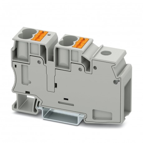
Images are for illustrative purposes only. Please refer to data sheet for details.
Reference: PTU 35/4X10
Code: 3002371
Manufacturer: PHOENIX CONTACT
Description:
Categories:
Brand new product in its original packaging covered by the warranties and certifications provided by PHOENIX CONTACT
LAST VIEWED
| Orderkey | 3002371 |
|---|---|
| Packing unit | 25 pc |
| Minimum order quantity | 25 pc |
| Note | Made to Order (non-returnable) |
| GTIN | 4055626430881 |
| Weight per Piece (excluding packing) | 9.990 g |
| Custom tariff number | 85369010 |
| Country of origin | IN (India) |
| Note | In the end application, the applicable safety regulations for overload and short-circuit protection on the connected conductors must be considered. |
|---|---|
| Number of levels | 1 |
| Number of connections | 5 |
| Nominal cross section | 16 mm² |
| Color | gray |
| Insulating material | PA |
| Flammability rating according to UL 94 | V0 |
| Rated surge voltage | 8 kV |
| Degree of pollution | 2 |
| Overvoltage category | III |
| Insulating material group | I |
| Maximum power dissipation for nominal condition | 4.06 W (the value is multiplied when connecting multiple levels) |
| Connection method | Screw connection |
| Connection in acc. with standard | IEC 60947-7-1 |
| Maximum load current | 101 A (The maximum load current must not be exceeded by the total current of all connected conductors.) |
| Nominal current IN | 101 A |
| Nominal voltage UN | 1000 V |
| Connection method | Push-in connection |
| Connection in acc. with standard | IEC 60947-7-1 |
| Maximum load current | 57 A |
| Nominal current IN | 57 A |
| Nominal voltage UN | 1000 V |
| Open side panel | No |
| Back of the hand protection | guaranteed |
| Finger protection | guaranteed |
| Result of surge voltage test | Test passed |
| Surge voltage test setpoint | 9.8 kV |
| Result of power-frequency withstand voltage test | Test passed |
| Power frequency withstand voltage setpoint | 2.2 kV |
| Result of the test for mechanical stability of terminal points (5 x conductor connection) | Test passed |
| Result of bending test | Test passed |
| Bending test rotation speed | 10 rpm |
| Bending test turns | 135 |
| Bending test conductor cross section/weight | 2.5 mm² / 0.7 kg |
| 10 mm² / 2 kg | |
| 35 mm² / 6.8 kg | |
| Tensile test result | Test passed |
| Conductor cross section tensile test | 2.5 mm² |
| Tractive force setpoint | 50 N |
| Conductor cross section tensile test | 10 mm² |
| Tractive force setpoint | 90 N |
| Conductor cross section tensile test | 35 mm² |
| Tractive force setpoint | 190 N |
| Result of tight fit on support | Test passed |
| Tight fit on carrier | NS 35 |
| Setpoint | 5 N |
| Result of voltage-drop test | Test passed |
| Requirements, voltage drop | ≤ 1.6 mV |
| Result of temperature-rise test | Test passed |
| Short circuit stability result | Test passed |
| Conductor cross section short circuit testing | 10 mm² |
| Short-time current | 1.2 kA |
| Conductor cross section short circuit testing | 16 mm² |
| Short-time current | 1.92 kA |
| Conductor cross section short circuit testing | 35 mm² |
| Short-time current | 4.2 kA |
| Result of aging test | Test passed |
| Ageing test for screwless modular terminal block temperature cycles | 192 |
| Result of thermal test | Test passed |
| Proof of thermal characteristics (needle flame) effective duration | 30 s |
| Oscillation, broadband noise test result | Test passed |
| Test specification, oscillation, broadband noise | DIN EN 50155 (VDE 0115-200):2008-03 |
| Test spectrum | Service life test category 2, bogie-mounted |
| Test frequency | f1= 5 Hz to f2= 250 Hz |
| ASD level | 6.12 (m/s2)2/Hz |
| Acceleration | 3.12 g |
| Test duration per axis | 5 h |
| Test directions | X-, Y- and Z-axis |
| Shock test result | Test passed |
| Test specification, shock test | DIN EN 50155 (VDE 0115-200):2008-03 |
| Shock form | Half-sine |
| Acceleration | 30g |
| Shock duration | 18 ms |
| Number of shocks per direction | 3 |
| Test directions | X-, Y- and Z-axis (pos. and neg.) |
| Relative insulation material temperature index (Elec., UL 746 B) | 130 °C |
| Temperature index of insulation material (DIN EN 60216-1 (VDE 0304-21)) | 130 °C |
| Static insulating material application in cold | -60 °C |
| Behavior in fire for rail vehicles (DIN 5510-2) | Test passed |
| Flame test method (DIN EN 60695-11-10) | V0 |
| Oxygen index (DIN EN ISO 4589-2) | >32 % |
| NF F16-101, NF F10-102 Class I | 2 |
| NF F16-101, NF F10-102 Class F | 2 |
| Surface flammability NFPA 130 (ASTM E 162) | passed |
| Specific optical density of smoke NFPA 130 (ASTM E 662) | passed |
| Smoke gas toxicity NFPA 130 (SMP 800C) | passed |
| Calorimetric heat release NFPA 130 (ASTM E 1354) | 28 MJ/kg |
| Fire protection for rail vehicles (DIN EN 45545-2) R22 | HL 1 - HL 3 |
| Fire protection for rail vehicles (DIN EN 45545-2) R23 | HL 1 - HL 3 |
| Fire protection for rail vehicles (DIN EN 45545-2) R24 | HL 1 - HL 3 |
| Fire protection for rail vehicles (DIN EN 45545-2) R26 | HL 1 - HL 3 |
| Connection method | Screw connection |
|---|---|
| Connection in acc. with standard | IEC 60947-7-1 |
| Screw thread | M6 |
| Tightening torque, min | 3.2 Nm |
| Tightening torque max | 3.7 Nm |
| Stripping length | 18 mm |
| Conductor cross section solid min. | 10 mm² |
| Conductor cross section solid max. | 35 mm² |
| Conductor cross section AWG min. | 8 |
| Conductor cross section AWG max. | 2 |
| Conductor cross section flexible min. | 10 mm² |
| Conductor cross section flexible max. | 35 mm² |
| Min. AWG conductor cross section, flexible | 8 |
| Max. AWG conductor cross section, flexible | 2 |
| Conductor cross section flexible, with ferrule without plastic sleeve min. | 10 mm² |
| Conductor cross section flexible, with ferrule without plastic sleeve max. | 35 mm² |
| Conductor cross section flexible, with ferrule with plastic sleeve min. | 10 mm² |
| Conductor cross section flexible, with ferrule with plastic sleeve max. | 35 mm² |
| 2 conductors with same cross section, solid min. | 1.5 mm² |
| 2 conductors with same cross section, solid max. | 16 mm² |
| Two conductors with the same cross section, AWG solid min. | 16 |
| Two conductors with the same cross section, AWG solid max. | 6 |
| 2 conductors with same cross section, stranded min. | 1.5 mm² |
| 2 conductors with same cross section, stranded max. | 10 mm² |
| Two conductors with the same cross section, AWG stranded, min. | 16 |
| Two conductors with the same cross section, AWG stranded, max. | 8 |
| 2 conductors with same cross section, stranded, ferrules without plastic sleeve, min. | 1.5 mm² |
| 2 conductors with same cross section, stranded, ferrules without plastic sleeve, max. | 10 mm² |
| Conductor cross section solid min. | 1 mm² |
| Conductor cross section solid max. | 16 mm² |
| Conductor cross section AWG min. | 16 |
| Conductor cross section AWG max. | 6 |
| Conductor cross section flexible min. | 4 mm² |
| Conductor cross section flexible max. | 10 mm² |
| Internal cylindrical gage | B9 |
| Connection method | Push-in connection |
| Connection in acc. with standard | IEC 60947-7-1 |
| Conductor cross section solid min. | 2.5 mm² |
| Conductor cross section solid max. | 16 mm² |
| Conductor cross section AWG min. | 20 |
| Conductor cross section AWG max. | 6 |
| Conductor cross section flexible min. | 2.5 mm² |
| Conductor cross section flexible max. | 10 mm² |
| Min. AWG conductor cross section, flexible | 20 |
| Max. AWG conductor cross section, flexible | 8 |
| Conductor cross section flexible, with ferrule without plastic sleeve min. | 2.5 mm² |
| Conductor cross section flexible, with ferrule without plastic sleeve max. | 10 mm² |
| Conductor cross section flexible, with ferrule with plastic sleeve min. | 2.5 mm² |
| Conductor cross section flexible, with ferrule with plastic sleeve max. | 10 mm² |
| Connection in acc. with standard | IEC 60947-7-1 |
|---|---|
| IEC 60947-7-1 | |
| Flammability rating according to UL 94 | V0 |
| Fire protection for rail vehicles (DIN EN 45545-2) R22 | HL 1 - HL 3 |
| Fire protection for rail vehicles (DIN EN 45545-2) R23 | HL 1 - HL 3 |
| Fire protection for rail vehicles (DIN EN 45545-2) R24 | HL 1 - HL 3 |
| Fire protection for rail vehicles (DIN EN 45545-2) R26 | HL 1 - HL 3 |
All ratings we receive from the items we offer are real and verified. A small gesture, but a lot of value. That's why we thank you for that minute you invest in leaving us your opinion and qualification about the products, because it helps us to continue improving and to offer you a service of even higher quality.
5/5 .
— CHE 5/6/26, 10:33 AM
Product:MTZ18-4VM DANFOSS REFRIGERATION Reciproc...
5/5 merci beaucoup
— sotitradim 11/29/25, 11:12 AM
Product:SL20,MNM,IP42,300lm,1H SL2MNM42H1C EATON...
4/5 a,azing to use it
— B rahul 10/4/25, 8:05 AM
Product:661601 LEGRAND URA21LED 70LM 1H IP42 NP
4/5 Amazing to use it
— B rahul 10/4/25, 8:04 AM
Product:661601 LEGRAND URA21LED 70LM 1H IP42 NP