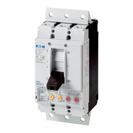
Application
Use in unearthed supply systems at 690 V
Circuit breaker frame type
Features
Protection unit
Motor drive optional
10.10 Temperature rise
The panel builder is responsible for the temperature rise calculation. Eaton will provide heat dissipation data for the devices.
10.11 Short-circuit rating
Is the panel builder's responsibility. The specifications for the switchgear must be observed.
10.12 Electromagnetic compatibility
Is the panel builder's responsibility. The specifications for the switchgear must be observed.
10.13 Mechanical function
The device meets the requirements, provided the information in the instruction leaflet (IL) is observed.
10.2.2 Corrosion resistance
Meets the product standard's requirements.
10.2.3.1 Verification of thermal stability of enclosures
Meets the product standard's requirements.
10.2.3.2 Verification of resistance of insulating materials to normal heat
Meets the product standard's requirements.
10.2.3.3 Resist. of insul. mat. to abnormal heat/fire by internal elect. effects
Meets the product standard's requirements.
10.2.4 Resistance to ultra-violet (UV) radiation
Meets the product standard's requirements.
10.2.5 Lifting
Does not apply, since the entire switchgear needs to be evaluated.
10.2.6 Mechanical impact
Does not apply, since the entire switchgear needs to be evaluated.
10.2.7 Inscriptions
Meets the product standard's requirements.
10.3 Degree of protection of assemblies
Does not apply, since the entire switchgear needs to be evaluated.
10.4 Clearances and creepage distances
Meets the product standard's requirements.
10.5 Protection against electric shock
Does not apply, since the entire switchgear needs to be evaluated.
10.6 Incorporation of switching devices and components
Does not apply, since the entire switchgear needs to be evaluated.
10.7 Internal electrical circuits and connections
Is the panel builder's responsibility.
10.8 Connections for external conductors
Is the panel builder's responsibility.
10.9.2 Power-frequency electric strength
Is the panel builder's responsibility.
10.9.3 Impulse withstand voltage
Is the panel builder's responsibility.
10.9.4 Testing of enclosures made of insulating material
Is the panel builder's responsibility.
Mounting Method
DIN rail (top hat rail) mounting optional
Built-in device plug-in technique
Plug-in unit
Climatic proofing
Damp heat, constant, to IEC 60068-2-78
Damp heat, cyclic, to IEC 60068-2-30
Equipment heat dissipation, current-dependent
Isolation
300 V AC (between the auxiliary contacts)
500 V AC (between auxiliary contacts and main contacts)
Ambient operating temperature - max
Ambient operating temperature - min
Ambient storage temperature - max
Ambient storage temperature - min
Number of auxiliary contacts (change-over contacts)
Number of auxiliary contacts (normally closed contacts)
Number of auxiliary contacts (normally open contacts)
Protection against direct contact
Finger and back-of-hand proof to DIN EN 50274/VDE 0106 part 110
Degree of protection
IP20 (basic degree of protection, in the operating controls area)
IP20
Direction of incoming supply
Electrical connection type of main circuit
Degree of protection (IP), front side
IP66 (with door coupling rotary handle)
IP40 (with insulating surround)
Degree of protection (terminations)
IP00 (terminations, phase isolator and strip terminal)
IP10 (tunnel terminal)
Terminal capacity (copper strip)
Min. 2 segements of 16 mm x 0.8 mm at rear-side connection (punched)
Max. 10 segments of 16 mm x 0.8 mm at box terminal
Max. 10 segments of 24 mm x 0.8 mm at rear-side connection (punched)
Min. 2 segments of 9 mm x 0.8 mm at box terminal
Max. 8 segments of 24 mm x 1 mm (2x) at box terminal
Lifespan, electrical
7500 operations at 690 V AC-1
5000 operations at 690 V AC-3
6500 operations at 415 V AC-3
10000 operations at 415 V AC-1
6500 operations at 400 V AC-3
10000 operations at 400 V AC-1
Functions
Systems, cable, selectivity and generator protection
Shock resistance
20 g (half-sinusoidal shock 20 ms)
Position of connection for main current circuit
Rated operational current for specified heat dissipation (In)
Short-circuit total breaktime
Rated short-time withstand current (t = 0.3 s)
Rated short-time withstand current (t = 1 s)
Short-circuit release delayed setting - max
Short-circuit release delayed setting - min
Short-circuit release non-delayed setting - max
Short-circuit release non-delayed setting - min
Terminal capacity (control cable)
0.75 mm² - 1.5 mm² (2x)
0.75 mm² - 2.5 mm² (1x)
Terminal capacity (copper busbar)
M8 at rear-side screw connection
Min. 16 mm x 5 mm direct at switch rear-side connection
Max. 24 mm x 8 mm direct at switch rear-side connection
Terminal capacity (copper solid conductor/cable)
6 mm² - 16 mm² (2x) at box terminal
10 mm² - 16 mm² (1x) at box terminal
10 mm² - 16 mm² (1x) direct at switch rear-side connection
6 mm² - 16 mm² (2x) direct at switch rear-side connection
16 mm² (1x) at tunnel terminal
Terminal capacity (aluminum solid conductor/cable)
16 mm² (1x) at tunnel terminal
Terminal capacity (copper stranded conductor/cable)
25 mm² - 185 mm² (1x) at 1-hole tunnel terminal
25 mm² - 70 mm² (2x) direct at switch rear-side connection
25 mm² - 185 mm² (1x) direct at switch rear-side connection
25 mm² - 185 mm² (1x) at box terminal
25 mm² - 70 mm² (2x) at box terminal
Terminal capacity (aluminum stranded conductor/cable)
25 mm² - 185 mm² (1x) at tunnel terminal
Short delay current setting (Isd) - max
Short delay current setting (Isd) - min
Instantaneous current setting (Ii) - max
Instantaneous current setting (Ii) - min
Number of operations per hour - max
Overload current setting (Ir) - max
Overload current setting (Ir) - min
Rated short-circuit breaking capacity Ics (IEC/EN 60947) at 230 V, 50/60 Hz
Rated short-circuit breaking capacity Ics (IEC/EN 60947) at 400/415 V, 50/60 Hz
Rated short-circuit breaking capacity Ics (IEC/EN 60947) at 440 V, 50/60 Hz
Rated short-circuit breaking capacity Ics (IEC/EN 60947) at 525 V, 50/60 Hz
Rated short-circuit breaking capacity Ics (IEC/EN 60947) at 690 V, 50/60 Hz
Rated short-circuit making capacity Icm at 400/415 V, 50/60 Hz
Rated short-circuit making capacity Icm at 440 V, 50/60 Hz
Rated short-circuit making capacity Icm at 525 V, 50/60 Hz
Rated short-circuit making capacity Icm at 690 V, 50/60 Hz
Optional terminals
Box terminal. Connection on rear. Tunnel terminal
Rated short-circuit making capacity Icm at 240 V, 50/60 Hz
Rated impulse withstand voltage (Uimp) at auxiliary contacts
Rated impulse withstand voltage (Uimp) at main contacts
Rated insulation voltage (Ui)