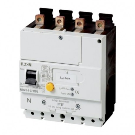
NZM1-4-XFI30U 104612 EATON ELECTRIC Earth-fault release, 30mA, 4p, bottom View larger
Images are for illustrative purposes only. Please refer to data sheet for details.

NZM1-4-XFI30U 104612 EATON ELECTRIC Earth-fault release, 30mA, 4p, bottom

NZM1-4-XFI30U

104612

EATON-MOELLER

Earth-fault release, 30mA, 4p, bottom

NZM1-4-XFI30U

More details


Low-voltage industrial components > Residual current release for power circuit breaker

Circuit Breakers NZM Accessories

* Brand new product in its original packaging covered by the warranties and certifications provided by EATON-MOELLER

Total price: $650.80
Unit price: $650.80

*This price is per unit and is the net value (not including taxes if applicable).

If our price is not the best, please ask us for a quote. Ask for a quotation

More info


Earth-fault release, 30mA, 4p, bottom
Optional accessories for the circuit-breaker series NZM offers a comprehensive portfolio of application options for use world wide. The mounting is always flexible and easy thanks to the modular function groups. Notes: approved according to IEC/EN 60947-2 not UL/CSA approved. Suitable for use in three- and single-phase systems. Pulse current sensitive according to core-balance principle. For 3 and 4 pole NZM1(-4) circuit-breakers and switch-disconnectors N1(-4).mains voltage independent Ue = 200 .. 415 V 50/60 Hz. At I △n = 0.03 A: delay time t v always fixed setting to 10 ms. Warning message > 30 % I △n by yellow LED. Trip indication max. 2 auxiliary contacts (HIAFI) can be fitted by user: N/O = M22-K01, N/C = M22-K10 are reset via the reset button. If the trip-indicating auxiliary contact in the fault current block is used, the N/C contacts operates as a N/O contact and the N/C contact operates as an N/O contact. Double contact not permissible. Not in combination with insulated enclosure or main switch assembly kit for side panel mounting with mounting bracket. NZM1-XFI...R can not be used in combination with lower cover NZM1-XUSA.NZM1-XFI…U not in combination with shunt or undervoltage release, early-make auxiliary contacts. Rated ultimate short-circuit breaking capacity is determined by fitted NZM1, NS1. When using a switch-disconnector N1, by the back-up fuse to be used. See technical data. Can be used for NZM1-4, N1-4

Delivery program

Description
Earth-fault release to IEC/EN 60947-2
not UL/CSA approved
Suitable for use in three-phase systems
Pulse-current sensitive type A according to core-balance principle
For 4 pole NZM1-4 circuit-breakers and N1-4 switch-disconnectors
Supply voltage-dependent Ue = 200 – 415 V 50/60 Hz
Control knobs, sealable.
Bottom mounting up to 100 A
Contact sequence
123N012
For use with
For use with
NZM1-4
N1-4
Pole
4 pole
Notes

With I△n= 0.03 A: delay time tvalways fixed setting at 10 ms.

Alarm message > 30 % I△nby yellow LED.

Trip indication max. 2 auxiliary contacts (HIAFI) can be fitted by user: N/O = M22-K01, N/C = M22-K10 are reset via the reset toggle lever.

If the trip-indicating auxiliary contact in the fault current block is used, the N/C contacts operates as a N/O contact and the N/C contact operates as an N/O contact.

Double contact not permissible.

Not in combination with insulated enclosure or main switch assembly kit for side panel mounting with mounting bracket

NZM1-XFI...R can not be used in combination with lower cover NZM1-XUSA.

NZM1-XFI…U not in combination with shunt or undervoltage release, early-make auxiliary contacts.

Rated ultimate short-circuit breaking capacity is determined by the fitted NZM1, NS1.

If a switch-disconnector N1 is applied by the back-up fuse to be used → Technical data.

Technical data

Electrical
Standards
IEC/EN 60947-2
IEC/EN 60947-2 annex B
Sensitivity
Pulse-current sensitive as per core-balance principle (type A)
Min. operating voltage [Ue]or detection of fault currents type A/AC
80 V (dependent on mains voltage)
Suitability for the application
in three-phase systems
Rated operational voltage [Ue]
200…415 (3~) V AC
Rated frequency [f]
50/60 Hz
Number of poles
4-pole
Rated current range [In]
15…100 A
Rated fault currents [ IΔn]
0.03 A
Detection range of the fault current
50/60 Hz
Rated ultimate short-circuit making capacity and rated ultimate short-circuit breaking capacity [IΔm]
= ICUA
Mechanical shock resistance (IEC 60068-2-27)
20 (half-sinusoidal shock 20 ms)
Lifespan, mechanical (50 % with fault current) [Operations]
20000
Mechanical
Standard front dimension
45 mm
Mounting
Bottom
Mounting position
Vertical and 90° in all directions
Supply
NZM1 from above
Degree of protection
IP20 in the operating component area
Ambient temperature
-5 - +40
Terminal capacityFlexible without ferrule
wie NZM1 Standardklemme mm2
Terminal capacityflexible with ferrules
such as NZM1 standard terminal mm2

Design verification as per IEC/EN 61439

Technical data for design verification
Operating ambient temperature min.
-5 °C
Operating ambient temperature max.
+40 °C
IEC/EN 61439 design verification
10.2 Strength of materials and parts10.2.2 Corrosion resistance
Meets the product standard's requirements.
10.2 Strength of materials and parts10.2.3.1 Verification of thermal stability of enclosures
Meets the product standard's requirements.
10.2 Strength of materials and parts10.2.3.2 Verification of resistance of insulating materials to normal heat
Meets the product standard's requirements.
10.2 Strength of materials and parts10.2.3.3 Verification of resistance of insulating materials to abnormal heat and fire due to internal electric effects
Meets the product standard's requirements.
10.2 Strength of materials and parts10.2.4 Resistance to ultra-violet (UV) radiation
Meets the product standard's requirements.
10.2 Strength of materials and parts10.2.5 Lifting
Does not apply, since the entire switchgear needs to be evaluated.
10.2 Strength of materials and parts10.2.6 Mechanical impact
Does not apply, since the entire switchgear needs to be evaluated.
10.2 Strength of materials and parts10.2.7 Inscriptions
Meets the product standard's requirements.
10.3 Degree of protection of ASSEMBLIES
Does not apply, since the entire switchgear needs to be evaluated.
10.4 Clearances and creepage distances
Meets the product standard's requirements.
10.5 Protection against electric shock
Does not apply, since the entire switchgear needs to be evaluated.
10.6 Incorporation of switching devices and components
Does not apply, since the entire switchgear needs to be evaluated.
10.7 Internal electrical circuits and connections
Is the panel builder's responsibility.
10.8 Connections for external conductors
Is the panel builder's responsibility.
10.9 Insulation properties10.9.2 Power-frequency electric strength
Is the panel builder's responsibility.
10.9 Insulation properties10.9.3 Impulse withstand voltage
Is the panel builder's responsibility.
10.9 Insulation properties10.9.4 Testing of enclosures made of insulating material
Is the panel builder's responsibility.
10.10 Temperature rise
The panel builder is responsible for the temperature rise calculation. Eaton will provide heat dissipation data for the devices.
10.11 Short-circuit rating
Is the panel builder's responsibility. The specifications for the switchgear must be observed.
10.12 Electromagnetic compatibility
Is the panel builder's responsibility. The specifications for the switchgear must be observed.
10.13 Mechanical function
The device meets the requirements, provided the information in the instruction leaflet (IL) is observed.

Technical data ETIM 7.0

Low-voltage industrial components (EG000017) / Residual current release for power circuit breaker (EC001021)
Electric engineering, automation, process control engineering / Low-voltage switch technology / Circuit breaker (LV < 1 kV) / Fault current switch for circuit breakers ([email protected] [AKF009013])
Rated control supply voltage Us at AC 50HZ
200 - 415 V
Rated control supply voltage Us at AC 60HZ
200 - 415 V
Rated control supply voltage Us at DC
0 - 0 V
Rated fault current
0.03 - 0.03 A
Max. power on-delay time
30 ms
Delay adjustable
No
Max. rated operation voltage Ue
415 V

Dimensions

1230DIM-49

Datasheet - PDF

Reviews (0)

No customer reviews for the moment.

Add Review
hide form
Rating:
Name:
Email:
Subject:
Text:
  Captcha
  Add review

All ratings we receive from the items we offer are real and verified. A small gesture, but a lot of value. That's why we thank you for that minute you invest in leaving us your opinion and qualification about the products, because it helps us to continue improving and to offer you a service of even higher quality.