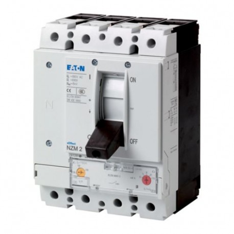
NZMB2-4-AF125-BT-NA 113011 EATON ELECTRIC Circuit-breaker, 4p, 125A, box terminals View larger
Images are for illustrative purposes only. Please refer to data sheet for details.

NZMB2-4-AF125-BT-NA 113011 EATON ELECTRIC Circuit-breaker, 4p, 125A, box terminals

NZMB2-4-AF125-BT-NA

113011

EATON-MOELLER

Circuit-breaker, 4p, 125A, box terminals

NZMB2-4-AF125-BT-NA

More details


Low-voltage industrial components > Power circuit-breaker for trafo/generator/installation protection

Circuit Breakers NZM

* Brand new product in its original packaging covered by the warranties and certifications provided by EATON-MOELLER

Total price: $752.48
Unit price: $752.48

*This price is per unit and is the net value (not including taxes if applicable).

If our price is not the best, please ask us for a quote. Ask for a quotation

More info


Automatic switch of power, 4p, 125A, terminals cloak
The circuit breakers of the power series NZM..-AF..NA covered with only four frame sizes all typical applications and are suitable for use all over the world. The assembly is flexible due to the functional groups modular. With overload circuit breaker for the protection of systems and cables. Release heat fixed. Notes: the switch complies with UL/CSA and IEC. The values of the power of opening the IEC are placed on the data plate of the machine.

Delivery program

Assortment
automatic switch of power
Protection function
protection of systems and cables
Standard/Approval
UL/CSA, IEC
Technical release
Trip unit circuit breaker
Installation technique
Fixed mount
Description
The switch complies with UL/CSA and IEC. The values of the power of opening the IEC are placed on the data plate of the machine.
Trip units thermal-regulated in the fixed Ir
Size
NZM2
Number of poles
4-pole
Standard equipment
Clamp coat
Power
SCCR 480Y/277 V 60 Hz [Icu]
25 kA
SCCR 480 V 60 Hz [Icu]
25 kA
Rated current = rated uninterrupted current [In= Theu]
One hundred twenty five
Neutral conductor [% of the phase conductor]
100 To
Field calibration
- Release thermal[Ther]
125 - 125
- Release thermalPhase conductor[Ther]
125 - 125
- Release thermalNeutral conductor [% of the phase conductor]Neutral conductor [% of the phase conductor]
100 To
Magnetic release[Therm]without delay[Thethe= Thenx ...]
6 - 10

Technical data

General
Compliance with the standards
IEC/EN 60947, VDE 0660
Protection against accidental contact
protection against contact with the fingers and back of hand per VDE 0106 part 100
Suitability to the climates
Moist heat, constant according to IEC 60068-2-78
The humid heat, cyclic according to IEC 60068-2-30
Ambient temperatureStorage ambient temperature
-40 - +70 °C
Ambient temperatureOperation
-25 - +70 °C
Shock resistance (half-wave, 10 ms) according to IEC 60068-2-27
20 (shock duration 20 ms) g
Slicer safe according to EN 61140between auxiliary contacts and main contacts
500 V AC
Slicer safe according to EN 61140between auxiliary contacts
300 V AC
Weight
3.5 kg
Mounting positionMounting position
Vertical and rotated 90° in each direction
with the module of differential protection XFI:
- NZM1, N1, NZM2, N2: vertical and rotated 90° in each direction
with a removable device:
- NZM1, N1, NZM2, N2: vertical, 90° right/left
with a removable device:
- NZM3, N3: vertical, 90° right/left
- NZM4, N4: vertical
with remote control:
- NZM2, N(S)2, NZM3, N(S)3, NZM4, N(S)4: vertical and rotated 90° in each direction

The sense of power
To pleasure
Degree of protectionUnit
in the field of control elements: IP20 (degree of protection base)
Degree of protectionHousing
frame: IP40
with a handle for control of the delayed door lock: IP66
Degree of protectionConnection terminals
Terminal tunnel: IP10
Phase separator and clamp strips: IP00
Circuit breakers power
Rated voltage impulse withstand [Uimp]Main circuit
8000 V
Rated voltage impulse withstand [Uimp]Auxiliary contacts
6000 V
Rated voltage [Uand]
440 V AC
Overvoltage category/pollution degree
III/3
Rated insulation voltage [Uthe]
690 V
Use in networks with no grounding
≦ 440 V
Power
Nominal power of closing under short-circuit [Thecm]240 V [Icm]
63 kA
Nominal power of closing under short-circuit [Thecm]400/415 V [Icm]
53 kA
Nominal power of closing under short-circuit [Thecm]440 V 50/60 Hz [Icm]
53 kA
Rated breaking capacity under short-circuit Thecn[Thecn]Icu to IEC/EN 60947 switching sequence OtCO [Icu]240 V, 50/60 Hz [Icu]
30 kA
Rated breaking capacity under short-circuit Thecn[Thecn]Icu to IEC/EN 60947 switching sequence OtCO [Icu]400/415 V, 50/60 Hz [Icu]
25 kA
Rated breaking capacity under short-circuit Thecn[Thecn]Icu to IEC/EN 60947 switching sequence OtCO [Icu]440 V, 50/60 Hz [Icu]
25 kA
Rated breaking capacity under short-circuit Thecn[Thecn]Ics to IEC/EN 60947 switching sequence OtCOtCO [Ics]240 V, 50/60 Hz [Ics]
30 kA
Rated breaking capacity under short-circuit Thecn[Thecn]Ics to IEC/EN 60947 switching sequence OtCOtCO [Ics]400/415 V, 50/60 Hz [Ics]
25 kA
Rated breaking capacity under short-circuit Thecn[Thecn]Ics to IEC/EN 60947 switching sequence OtCOtCO [Ics]440 V 50/60 Hz [Ics]
18.5 kA
Rated breaking capacity under short-circuit Thecn[Thecn]Max. NH-fuse
355 A gG/gL
Rated breaking capacity under short-circuit Thecn[Thecn]
Maximum safety, when the short-circuit current expected at the point of installation exceeds the breaking capacity of the circuit breaker of power.
Technical data, to the difference of the products for the market in the IEC
Power switches NA (UL489, CSA 22.2 No. 5.1)
Short-circuit current rating SCCR
SCCR 240 V 60 Hz [Icu]
35 kA
Technical data, to the difference of the products for the market in the IEC
Power switches NA (UL489, CSA 22.2 No. 5.1)
Short-circuit current rating SCCR
SCCR 480Y/277 V 60 Hz [Icu]
25 kA
Technical data, to the difference of the products for the market in the IEC
Power switches NA (UL489, CSA 22.2 No. 5.1)
Short-circuit current rating SCCR
SCCR 480 V 60 Hz [Icu]
25 kA
Use category according to IEC/EN 60947-2
To
Duration, mechanical (shutter max. 50% on the part of the release (A/U) [Operations]
Twenty thousand
Duration, electricalAC-1400 V 50/60 Hz [Operations]
Seven thousand five hundred
Duration, electricalAC-1415 V 50/60 Hz [Operations]
Ten thousand
Duration, electricalAC-3415 V 50/60 Hz [Operations]
Six thousand five hundred
Duration, electricalMax. switching frequency [op/h]
120 man/h
The total time of interruption short circuit
< 10 ms
Connection cross-sections
Standard equipment
Clamp coat
Cable circular CuClamp coatHard
1 x (12 - 6) mmTwo
Cable circular CuClamp coatFlexible
1 x (4 - 350) mmTwo
Cable circular CuTerminal tunnelHard
1 x 16 mmTwo
Cable circular CuTerminal tunnelflexibleflexible
1 x (4 - 350) mmTwo
Cable circular CuConnection bolt and connection backdirectly on the switchhard
1 x (11 - 6) mmTwo
Cable circular CuConnection bolt and connection backdirectly on the switchflexible
1 x (4 - 3/0) mmTwo
Cable in aluminium or copperTerminal tunnelhard
1 x 16 mmTwo
Cable in aluminium or copperConnection bolt and connection backStrip copper, perforated [min.]
2 x 16 x 0.8 mm
Cable in aluminium or copperConnection bolt and connection backStrip copper, perforated [max.]
10 x 16 x 0.8 mm
The foil strip of copper (number of slats x width x thickness slat)Clamp coat [min.]
2 x 9 x 0.8 mm
The foil strip of copper (number of slats x width x thickness slat)Clamp cloak [max.]
10 x 16 x 0.8 mm
The foil strip of copper (number of slats x width x thickness slat)Connection bolt and connection backStrip copper, perforated [min.]
2 x 16 x 0.8 mm
The foil strip of copper (number of slats x width x thickness slat)Connection bolt and connection backStrip copper, perforated [max.]
10 x 16 x 0.8 mm
The copper bar (width x depth) [mm]Connection bolt and connection backLink to bolt
M8
The copper bar (width x depth) [mm]Connection bolt and connection backdirectly on the switch [min.]
16 x 5 mm
The copper bar (width x depth) [mm]Connection bolt and connection backdirectly on the switch [max.]
20 x 5 mm
Control cables
1 x (18 - 14)
2 x (18 - 16) mmTwo
Design checks according to IEC/EN 61439

Technical data for design checks
The nominal current of use for the data related to dissipation [Then]
One hundred twenty five
Dissipation of the device, as a function of the current [Pvid]
27.61 W
Temperature service environment min.
-25 °C
Ambient temperature max service.
+70 °C
Design checks per IEC/EN 61439
10.2 the Suitability of materials and components10.2.2 Resistance to corrosion
The requirements of the product standard are met.
10.2 the Suitability of materials and components10.2.3.1 Resistance of the housing to the heat
The requirements of the product standard are met.
10.2 the Suitability of materials and components10.2.3.2 Resistance of insulating materials to heat levels normal
The requirements of the product standard are met.
10.2 the Suitability of materials and components10.2.3.3 Resistance of insulating materials to heat levels extraordinary
The requirements of the product standard are met.
10.2 the Suitability of materials and components10.2.4 Resistance to UV irradiation
The requirements of the product standard are met.
10.2 the Suitability of materials and components10.2.5 Lifting
Not applicable since the entire electrical panel should be evaluated.
10.2 the Suitability of materials and components10.2.6 Proof
Not applicable since the entire electrical panel should be evaluated.
10.2 the Suitability of materials and components10.2.7 Labeling
The requirements of the product standard are met.
10.3 Degree of protection provided by enclosures
Not applicable since the entire electrical panel should be evaluated.
10.4 Pathways of dispersion-air and surface
The requirements of the product standard are met.
10.5 Protection against electric shock
Not applicable since the entire electrical panel should be evaluated.
10.6 flush Mounting of appliances
Not applicable since the entire electrical panel should be evaluated.
10.7 internal Circuits and connections
Is the responsibility of the manufacturer of the electrical panel.
10.8 Connections for conductors introduced from the outside
Is the responsibility of the manufacturer of the electrical panel.
10.9 insulation properties10.9.2 dielectric strength at network frequency
Is the responsibility of the manufacturer of the electrical panel.
10.9 insulation properties10.9.3 Voltage impulse
Is the responsibility of the manufacturer of the electrical panel.
10.9 insulation properties10.9.4 Testing of enclosures of insulating material
Is the responsibility of the manufacturer of the electrical panel.
10.10 Heating
The calculation of the overheating is the responsibility of the manufacturer of the electrical panel. Eaton provides data on the dissipation of the equipment.
10.11 Resistance to short circuit
Is the responsibility of the manufacturer of the electrical panel. Respect the default values of the equipment.
10.12 EMC
Is the responsibility of the manufacturer of the electrical panel. Respect the default values of the equipment.
10.13 mechanical Function
For the unit requirements are met while respecting the directions of the assembly instructions (THE).

Technical data according to ETIM 7.0

electrical equipment in low-voltage (EG000017) / circuit breaker for protection of transformers, generators, and equipment (EC000228)
The Technique Of Ar., Elem., Energy, Tech. Comm., Network And Proc. Pipeline / Switch Technology, Low Voltage / Power circuit Breakers (Ns, < 1 Hp) / power Switch to trans., generat. and sett. plants ([email protected] [AJZ716013])
nominal continuous current Iu
One hundred twenty five
rated voltage
690 - 690 V
the current limit nominal switching to the short circuit at 400 V, 50 Hz
25 kA
adjustment range of trip unit overload
125 - 125
the range of adjustment of the activator of a short-circuit with short delay
750 - 1250 A
the range of adjustment of the activator short-circuit non-time delay
6 - 10 To
protection from earth fault detector integrated
no
type of connection circuit in the main electrical
clamp frame
the type of construction of the device
recessed luminaire, a technique for fixed installation
suitable for mounting on hat
no
mounting rail to DIN optional
no
number of auxiliary contacts, the contacts of the rest
Zero
number of auxiliary contacts, closing contacts
Zero
number of auxiliary contacts, power inverters
Zero
indicator intervention this
no
with undervoltage release
no
number of poles
Four
the location of the connection for the electrical circuit to the main
in front of
the execution of the drive element
rocker
complete device with safety unit
yes
motor drive integrated
no
motor drive optional
yes
degree of protection (IP)
IP20

Approvals

Product Standards
UL 489; CSA-C22.2 No. 5-09; IEC 60947-2; CE marking
UL File No.
E31593
UL Category Control No.
DIVQ
CSA File No.
-
CSA Class No.
-
North America Certification
UL listed
Specially designed for North America
Yes
Suitable for
Feeder circuits, branch circuits
Current Limiting Circuit-Breaker
Yes
Max. Voltage Rating
480 V
Degree of Protection
IEC: IP20; UL/CSA Type: -

Characteristic curves

Feature
123U176
Feature
1230DIA-85
Feature
1230DIA-80

Size

123X508
① The Space-off, the minimum safety distance compared to other surfaces
② The minimum safety Distance with respect to neighbouring parts
123X341

Datasheet - PDF

Title: Size: Type:
NZMB2-4-AF125-BT-NA 113011 EN_113011.pdf 614 Kbytes   NZMB2-4-AF125-BT-NA  113011 EN_113011.pdf

Reviews (0)

No customer reviews for the moment.

Add Review
hide form
Rating:
Name:
Email:
Subject:
Text:
  Captcha
  Add review

All ratings we receive from the items we offer are real and verified. A small gesture, but a lot of value. That's why we thank you for that minute you invest in leaving us your opinion and qualification about the products, because it helps us to continue improving and to offer you a service of even higher quality.