
No products
Product successfully added to your shopping cart


 View larger

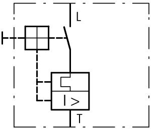
PKZM4-25-CB 132592 EATON ELECTRIC Circuit-breaker, 3p, Ir 16-25A, NA type
PKZM4-25-CB
132592
XTPR025DCBNL
EATON-MOELLER
Circuit-breaker, 3p, Ir=16-25A, NA type
PKZM4-25-CB
Circuit-breaker, Ir= 16 - 25 A, Screw terminals, Terminations: IP2X
Low-voltage industrial components > Power circuit-breaker for trafo/generator/installation protection
Circuit Breakers PKZ
* Brand new product in its original packaging covered by the warranties and certifications provided by EATON-MOELLER
Related products
▲More info
▲Delivery program
PKZM4 circuit-breakers up to 32 A according to 489
 [Ir]
[Ir] [Irm]max. [Irm]
Technical data
Damp heat, cyclic, to IEC 60068-2-30

2 x (0.75 - 16) mm2
2 x (0.75 - 16) mm2
Design verification as per IEC/EN 61439
Technical data ETIM 7.0
Approvals
Characteristics

1: Minimum level, 3-phase
2: Maximum level, 3-phase
3: Minimum marker, 2-phase
4: Highest marker, 2-phase


Let-through energy
Datasheet - PDF
▲| Title: | Size: | Type: |
|---|---|---|
| PDF EATON SWITCHING PROTECTING MOTORS EN.pdf | 34 Mbytes |

|
| PKZM4-25-CB XTPR025DCBNL 132592 EN_132592.pdf | 404 Kbytes |
|
Reviews (0) ▲
No customer reviews for the moment.
| Rating: |
|
| Name: | |
| Email: | |
| Subject: | |
| Text: | |
| Do you recommend this product to buy? | |
|
|
|
| Add review | |
All ratings we receive from the items we offer are real and verified. A small gesture, but a lot of value. That's why we thank you for that minute you invest in leaving us your opinion and qualification about the products, because it helps us to continue improving and to offer you a service of even higher quality.