
Cart
0
Product
Products
(empty)
No products
$0.00
Total
Product successfully added to your shopping cart
Quantity
Total
There are 0 items in your cart.
There is 1 item in your cart.
Total products
Total


 View larger

NZMN1-S1,2-CNA 103025 EATON ELECTRIC Circuit-breaker, 3p, 1, 2A
NZMN1-S1,2-CNA
103025
EATON-MOELLER
Circuit-breaker, 3p, 1, 2A
NZMN1-S1,2-CNA
Low-voltage industrial components > Motor protection circuit-breaker
Circuit Breakers NZM
* Brand new product in its original packaging covered by the warranties and certifications provided by EATON-MOELLER
More info
▲Circuit-breaker, 3p, 1, 2A
Series NZM..-S..CNA circuit-breakers cover all application cases with just four compact sizes and are suitable for use in the worldwide market. Modular function groups always make mounting flexible. With magnetic short-circuit release in connection with overload relay. With short-circuit release lacking overload trip. Notes: Switches conform to UL/CSA as well as IEC regulations. The rating plate contains IEC switching performance values.
Delivery program
Product range
Circuit-breaker
Protective function
Short-circuit protection
Standard/Approval
UL/CSA
Installation type
Fixed
Release system
Thermomagnetic release
Description
This circuit-breaker is only allowed to be used for UL/CSA applications.
Motor protection in conjunction with contactor and overload relay
With short-circuit release
Without overload release Ir
Motor protection in conjunction with contactor and overload relay
With short-circuit release
Without overload release Ir
Number of poles
3 pole
Standard equipment
Box terminal
Rated current = rated uninterrupted current [In= Iu]
1.2 A
Setting range
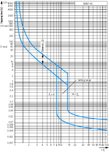
Short-circuit releases [Irm]Non-delayed
 [Ii= Inx …]
[Irm]Non-delayed[Ii= Inx …] 7 - 12
Technical data
General
Standards
UL/CSA
Protection against direct contact
Finger and back of hand proof to VDE 0106 Part 100
Climatic proofing
Damp heat, constant, to IEC 60068-2-78
Damp heat, cyclic, to IEC 60068-2-30
Damp heat, cyclic, to IEC 60068-2-30
Ambient temperatureAmbient temperature, storage
- 40 - + 70 °C
Ambient temperatureOperation
-25 - +70 °C
Mechanical shock resistance (10 ms half-sinusoidal shock) according to IEC 60068-2-27
20 (half-sinusoidal shock 20 ms) g
Safe isolation to EN 61140Between auxiliary contacts and main contacts
500 V AC
Safe isolation to EN 61140between the auxiliary contacts
300 V AC
Mounting positionMounting position
| Vertical and 90° in all directions | |
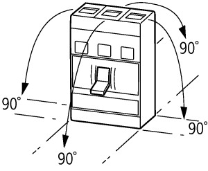 | With XFI earth-fault release: |
| - NZM1, N1, NZM2, N2: vertical and 90° in all directions | |
| with plug-in unit | |
| - NZM1, N1, NZM2, N2: vertical, 90° right/left | |
| with withdrawable unit: | |
| - NZM3, N3: vertical, 90° right/left | |
| - NZM4, N4: vertical | |
| with remote operator: | |
| - NZM2, N(S)2, NZM3, N(S)3, NZM4, N(S)4: vertical and 90° in all directions | |
Direction of incoming supply
as required
Degree of protectionDevice
In the operating controls area: IP20 (basic degree of protection)
Degree of protectionEnclosures
With insulating surround: IP40
With door coupling rotary handle: IP66
With door coupling rotary handle: IP66
Degree of protectionTerminations
Tunnel terminal: IP10
Phase isolator and strip terminal: IP00
Phase isolator and strip terminal: IP00
Other technical data (sheet catalogue)
Circuit-breakers
Rated surge voltage invariability [Uimp]Main contacts
6000 V
Rated surge voltage invariability [Uimp]Auxiliary contacts
6000 V
Rated operational voltage [Ue]
690 V AC
Overvoltage category/pollution degree
III/3
Rated insulation voltage [Ui]
690 V
Switching capacity
Lifespan, mechanical(of which max. 50 % trip by shunt/undervoltage release) [Operations]
20000
Lifespan, electricalAC--3400 V 50/60 Hz [Operations]
7500
Lifespan, electricalAC--3415 V 50/60 Hz [Operations]
7500
Lifespan, electricalAC--3690 V 50/60 Hz [Operations]
5000
Lifespan, electricalMax. operating frequency
120 Ops/h
Total break time at short-circuit
< 10 ms
Terminal capacity
Standard equipment
Box terminal
Round copper conductorBox terminalSolid
1 x (12 … 6) mm2
Round copper conductorBox terminalStranded
1 x (4 … 2/0) mm2
Round copper conductorTunnel terminalSolid
1 x 6 mm2
Round copper conductorTunnel terminalStrandedStranded
1 x (4 … 3/0) mm2
Round copper conductorBolt terminal and rear-side connectionDirect on the switchSolid
1 x (12 … 6)
2 x (9 … 6) mm2
2 x (9 … 6) mm2
Round copper conductorBolt terminal and rear-side connectionDirect on the switchStranded
1 x (4 … 2/0) mm2
Al conductors, Cu cableTunnel terminalSolid
1 x 16 mm2
Cu strip (number of segments x width x segment thickness)Box terminal [min.]
2 x 9 x 0.8 mm
Cu strip (number of segments x width x segment thickness)Box terminal [max.]
9 x 9 x 0.8 mm
Copper busbar (width x thickness) [mm]Bolt terminal and rear-side connectionScrew connection
M6
Copper busbar (width x thickness) [mm]Bolt terminal and rear-side connectionDirect on the switch [min.]
12 x 5 mm
Copper busbar (width x thickness) [mm]Bolt terminal and rear-side connectionDirect on the switch [max.]
16 x 5 mm
Control cables
1 x (18 … 14)
2 x (18 … 16) mm2
2 x (18 … 16) mm2
Design verification as per IEC/EN 61439
Technical data for design verification
Rated operational current for specified heat dissipation [In]
1.2 A
Equipment heat dissipation, current-dependent [Pvid]
1.78 W
Operating ambient temperature min.
-25 °C
Operating ambient temperature max.
+70 °C
IEC/EN 61439 design verification
10.2 Strength of materials and parts10.2.2 Corrosion resistance
Meets the product standard's requirements.
10.2 Strength of materials and parts10.2.3.1 Verification of thermal stability of enclosures
Meets the product standard's requirements.
10.2 Strength of materials and parts10.2.3.2 Verification of resistance of insulating materials to normal heat
Meets the product standard's requirements.
10.2 Strength of materials and parts10.2.3.3 Verification of resistance of insulating materials to abnormal heat and fire due to internal electric effects
Meets the product standard's requirements.
10.2 Strength of materials and parts10.2.4 Resistance to ultra-violet (UV) radiation
Meets the product standard's requirements.
10.2 Strength of materials and parts10.2.5 Lifting
Does not apply, since the entire switchgear needs to be evaluated.
10.2 Strength of materials and parts10.2.6 Mechanical impact
Does not apply, since the entire switchgear needs to be evaluated.
10.2 Strength of materials and parts10.2.7 Inscriptions
Meets the product standard's requirements.
10.3 Degree of protection of ASSEMBLIES
Does not apply, since the entire switchgear needs to be evaluated.
10.4 Clearances and creepage distances
Meets the product standard's requirements.
10.5 Protection against electric shock
Does not apply, since the entire switchgear needs to be evaluated.
10.6 Incorporation of switching devices and components
Does not apply, since the entire switchgear needs to be evaluated.
10.7 Internal electrical circuits and connections
Is the panel builder's responsibility.
10.8 Connections for external conductors
Is the panel builder's responsibility.
10.9 Insulation properties10.9.2 Power-frequency electric strength
Is the panel builder's responsibility.
10.9 Insulation properties10.9.3 Impulse withstand voltage
Is the panel builder's responsibility.
10.9 Insulation properties10.9.4 Testing of enclosures made of insulating material
Is the panel builder's responsibility.
10.10 Temperature rise
The panel builder is responsible for the temperature rise calculation. Eaton will provide heat dissipation data for the devices.
10.11 Short-circuit rating
Is the panel builder's responsibility. The specifications for the switchgear must be observed.
10.12 Electromagnetic compatibility
Is the panel builder's responsibility. The specifications for the switchgear must be observed.
10.13 Mechanical function
The device meets the requirements, provided the information in the instruction leaflet (IL) is observed.
Technical data ETIM 7.0
Low-voltage industrial components (EG000017) / Motor protection circuit-breaker (EC000074)
Electric engineering, automation, process control engineering / Low-voltage switch technology / Circuit breaker (LV < 1 kV) / Motor protection circuit-breaker ([email protected] [AGZ529016])
Overload release current setting
0 - 0 A
Adjustment range undelayed short-circuit release
7 - 12 A
With thermal protection
No
Phase failure sensitive
No
Switch off technique
Magnetic
Rated operating voltage
690 - 690 V
Rated permanent current Iu
1.2 A
Rated operation power at AC-3, 230 V
0.18 kW
Rated operation power at AC-3, 400 V
0.37 kW
Type of electrical connection of main circuit
Other
Type of control element
Rocker lever
Device construction
Built-in device fixed built-in technique
With integrated auxiliary switch
No
With integrated under voltage release
No
Number of poles
3
Rated short-circuit breaking capacity lcu at 400 V, AC
50 kA
Degree of protection (IP)
IP20
Height
165.5 mm
Width
90 mm
Depth
88 mm
Approvals
Product Standards
UL 489; CSA-C22.2 No. 5-09
UL File No.
E31593
UL Category Control No.
DKPU2
CSA File No.
022086
CSA Class No.
1432-01
North America Certification
UL recognized, CSA certified
Conditions of Acceptability
Only used in motor circuits in conjunction with suitable contactor and overload relay. SCCR value applies for complete combination starter only, consisting of instantaneous trip circuit breaker, contactor and overload relay.
Specially designed for North America
Yes
Suitable for
Branch circuits, feeder circuits
Current Limiting Circuit-Breaker
No
Max. Voltage Rating
480Y/277 V
Degree of Protection
UL/CSA Type: -
Characteristics
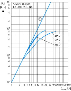
Characteristic curve
Short-circuit protection only!
Characteristic curve
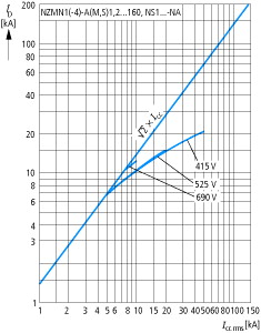
Characteristic curve
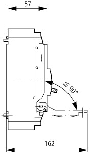
Dimensions
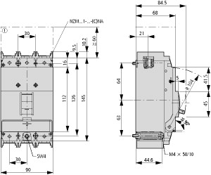
① Blow out area, minimum clearance to adjacent parts
Datasheet - PDF
▲| Title: | Size: | Type: |
|---|---|---|
| NZMN1-S1,2-CNA 103025 EN_103025.pdf | 565 Kbytes |
 |
Reviews (0) ▲
No customer reviews for the moment.
Add Review
hide form
| Rating: |
|
| Name: | |
| Email: | |
| Subject: | |
| Text: | |
| Do you recommend this product to buy? | |
|
|
|
| Add review | |
All ratings we receive from the items we offer are real and verified. A small gesture, but a lot of value. That's why we thank you for that minute you invest in leaving us your opinion and qualification about the products, because it helps us to continue improving and to offer you a service of even higher quality.