Keine Artikel
Produkt wurde in den Korb gelegt
 Vergrößern
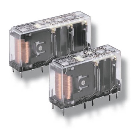
P7SA-14F 377194 OMRON Grundlage G7SA 6polos DIN-Schiene Schraube
P7SA-14F
377194
P7SA14F
OMRON
Grundlage G7SA 6polos DIN-Schiene Schraube
Sicherheitstechnik > G7S
* Neues Produkt in der Originalverpackung mit allen Garantien und Zertifizierungen von OMRON
Mehr Infos
▲Sicherheitsrelais mit zwangsgeführten Kontakten
Die schmalen Relais der Serie G7SA mit zwangsgeführten Kontakten stehen als vier- oder sechspolige Ausführungen mit verschiedenen Kontaktkombinationen und verstärkter Isolierung zur Verfügung. Die Anordnung der Leiterplattenanschlüsse erfolgte in Hinblick auf ein möglichst einfaches Leiterplatten-Layout. Diese Relais können direkt eingelötet oder unter Verwendung der Sockel P7SA benutzt werden.
- Zwangsgeführte Kontakte
- Entspricht EN 50205
- 6 A bei 240 V AC und 6 A bei 24 V DC (Ohmsche Last)
- Verstärkte Isolierung zwischen Spulen- und Kontaktanschlüssen
- Vier- und sechspolige Ausführungen, Spulen mit geringer Leistungsaufnahme
- Sockel mit Push-in-Technik verfügbar
Ordering information
Relays with forcibly guided contacts
24 VDC1 | |||||
Sockets
Specifications
Coil
Note:Refer to datasheet for details
Contacts
Relays with forcibly guided contacts
100 mΩ max. (The contact resistance was measured with 1 A at 5 VDC using the voltage-drop method.) | ||
Operating time2 | ||
Response time1 | 10 ms max. | |
Release time1 | ||
100 MΩ min. (at 500 VDC) (The insulation resistance was measured with a 500 VDC megger at the same places that the dielectric strength was | ||
| Between coil contacts/different poles: 4,000 VAC, 50/60 Hz for 1 min Between contacts of same polarity: 1,500 VAC, 50/60 Hz for 1 min | ||
10,000,000 operations min. (at approx. 36,000 operations/hr) | ||
100,000 operations min. (at the rated load and approx. 1,800 operations/hr) | ||
Min. permissible load5 | ||
Ambient temperature6 | ||
Note:The values listed above are initial values.
Please check Omron in the Internet for updated information on product reliability data and the SISTEMA libraries: http://industrial.omron.eu/safety
Datasheet - PDF
▲| Titel: | Größe: | Typ: |
|---|---|---|
| P7SA-14F P7SA14F 377194 | 240 Kbytes |
 |
| P7SA-14F P7SA14F 377194 j120_g7sa_relays_with_forcibly_guided_contacts_datasheet_de.pdf | 944 Kbytes |
 |
Bewertungen (0) ▲
Es gibt keine Produktbewertungenvor.
| Wertung: |


|
| Name: | |
| E-Mail : | |
| Betreff: | |
| Text: | |
| Haben Sie dieses Produkt empfehlen zu kaufen? | |
|
|
|
| Bewertung abgeben | |
Alle Bewertungen wir von den Einzelteilen erhalten wir anbieten, sind real und verifiziert. Eine kleine Geste, aber sehr wertvoll. Also danke für die Minute, die Sie in, dass Sie uns Ihre Meinung und Bewertung von Produkten ausgeben, weil es mir hilft, weiter zu verbessern und noch mehr Servicequalität zu bieten.


