
Sem produtos
Produto adicionado com sucesso ao seu carrinho de compras


 Ver maior

A4EG-BE2R041 247805 OMRON Produtos de Segurança, validação Comando de parada de emergência
A4EG-BE2R041
247805
OMRON
Produtos de Segurança, validação Comando de parada de emergência
Produtos de Segurança > Outros Segurança
* Produto novo em sua embalagem original com todas as garantias e certificações de OMRON
Mais informação
▲Módulo de comutação de dispositivos de segurança
O controlador de segurança que suporta o modo de manutenção e o modo de funcionamento normal de forma segura.
- Dois modos de funcionamento para suportar a comutação automática para aplicações com colaboração entre máquina e trabalhador e comutação manual para aplicações com limitações no funcionamento, como a manutenção
- Diagnósticos LED claros de todas as entradas e saídas
- Aplicável até à Categoria 4 de acordo com a norma EN 954-1
Enabling grip switches
Safety guard switching units
Safety outputs1 | Auxiliary outputs2 | Max. OFF | ||||||
|---|---|---|---|---|---|---|---|---|
OFF-delayed4 | ||||||||
Specifications
Ratings of guard switching unit
Power input
Inputs
Operating voltage: 20.4 VDC to 26.4 VDC, internal impedance: approx. 2.8 kΩ | |
Outputs
Application example
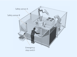
Automatic switching mode
Worker is loading and unloading the machine manually. When loading is finished, robot cycle is started manually by the worker. When robots return to their home position, loading cycle is selected automatically.
Loading condition: Safety sensor B is not active, safety sensor A is active because the robots are not allowed to move to the loading area while the worker loads the machine. So the worker is safe because safety sensor A is active.
Robot work condition: Safety sensor B is active, safety sensor A is not active because the worker is not allowed to move to the loading area when the robots work. So the worker is safe because safety sensor B stops the machine if he moves to the loading area.
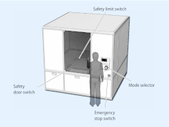
Manual switching mode
Worker has to do maintenance in this machine. While maintenance, it is necessary to move the machine in a limited way. The worker has to select automatic mode or manual mode manually by using the mode selector switch.
Operation steps:
1)Select maintenance mode by using the mode selector
2)Open the door to do the maintenance while the machine still is able to operate in a limited way (monitoring of limited movement by using the safety limit switch).
3)Close the cover after finishing maintenance
4)Select automatic mode by using the mode selector
E-Stop conditions:
a)open the door while not in maintenance mode
b)the machine actuates the limit switch (breaks the limit).
c)the Enabling grip switch A4EG is actuated to stop the machine in emergency condition.
Datasheet - PDF
▲| Título: | Tamanho: | Tipo: |
|---|---|---|
| A4EG-BE2R041 247805 | 240 Kbytes |
 |
| A4EG-BE2R041 247805 a4eg_datasheet_en.pdf | 3 Mbytes |
|
Avaliações: (0) ▲
Não há comentários do produto ainda.
| Avaliação: |
|
| Nome: | |
| Email: | |
| Título: | |
| Opinión: | |
| Você recomendaria esse produto para comprar? | |
|
|
|
| Adicionar avaliação | |
Todas as classificações que recebemos a partir dos itens que oferecemos são reais e verificadas. Um pequeno gesto, mas muito valioso. Então, obrigado por esse minuto você gasta em deixar-nos a sua opinião e classificação de produtos, porque nos ajuda a continuar a melhorar e oferecer maior qualidade de serviço.