Nessun prodotto
Prodotto aggiunto al tuo carrello
 Visualizza ingrandito
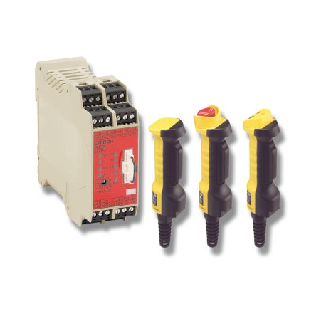
A4EG-BE2R041 247805 OMRON Security Products, convalida Comando E-stop
A4EG-BE2R041
247805
OMRON
Security Products, convalida Comando E-stop
Sicurezza > Altri sicurezza
* Prodotto nuovo nel suo imballaggio d'origine con tutte le garanzie e certificazioni de OMRON
Dettagli
▲Modulo di commutazione per barriere di sicurezza
Il modulo di sicurezza favorisce le modalità di manutenzione e di funzionamento normale in tutta sicurezza.
- Due modalità di funzionamento per favorire la commutazione automatica per le applicazioni che prevedono l'interazione tra macchine e operatori e la commutazione manuale per applicazioni con limitazioni di funzionamento, come in fase di manutenzione
- Diagnostica LED chiara di tutte gli ingressi e le uscite
- Applicabile fino alla categoria 4 in base a EN 954-1
Enabling grip switches
Safety guard switching units
Safety outputs1 | Auxiliary outputs2 | Max. OFF | ||||||
|---|---|---|---|---|---|---|---|---|
OFF-delayed4 | ||||||||
Specifications
Ratings of guard switching unit
Power input
Inputs
Operating voltage: 20.4 VDC to 26.4 VDC, internal impedance: approx. 2.8 kΩ | |
Outputs
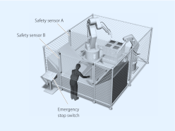
Application example
Automatic switching mode
Worker is loading and unloading the machine manually. When loading is finished, robot cycle is started manually by the worker. When robots return to their home position, loading cycle is selected automatically.
Loading condition: Safety sensor B is not active, safety sensor A is active because the robots are not allowed to move to the loading area while the worker loads the machine. So the worker is safe because safety sensor A is active.
Robot work condition: Safety sensor B is active, safety sensor A is not active because the worker is not allowed to move to the loading area when the robots work. So the worker is safe because safety sensor B stops the machine if he moves to the loading area.

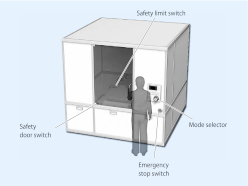
Manual switching mode
Worker has to do maintenance in this machine. While maintenance, it is necessary to move the machine in a limited way. The worker has to select automatic mode or manual mode manually by using the mode selector switch.
Operation steps:
1)Select maintenance mode by using the mode selector
2)Open the door to do the maintenance while the machine still is able to operate in a limited way (monitoring of limited movement by using the safety limit switch).
3)Close the cover after finishing maintenance
4)Select automatic mode by using the mode selector
E-Stop conditions:
a)open the door while not in maintenance mode
b)the machine actuates the limit switch (breaks the limit).
c)the Enabling grip switch A4EG is actuated to stop the machine in emergency condition.

Datasheet - PDF
▲| Titolo: | Dimensione: | Tipo: |
|---|---|---|
| A4EG-BE2R041 247805 | 240 Kbytes |
 |
| A4EG-BE2R041 247805 a4eg_datasheet_en.pdf | 3 Mbytes |
 |
Recensioni: (0) ▲
Nessun commento per il momento.
| Valutazione: |


|
| Nome: | |
| Email: | |
| Titolo: | |
| Testo: | |
| Mi consiglia questo prodotto da acquistare? | |
|
|
|
| Inserisci recensione | |
Tutti i feedback che riceviamo dagli elementi che offriamo sono reali e verificati. Un piccolo gesto, ma di grande valore. Quindi grazie per quel minuto si spende in noi lasciare il vostro parere e punteggio sui prodotti, perché ci aiuta a continuare a migliorare e di offrire ancora maggiore qualità del servizio.


