Nessun prodotto
Prodotto aggiunto al tuo carrello
 Visualizza ingrandito
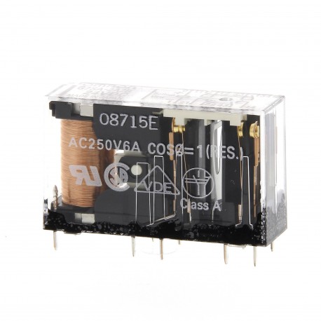
G7SA-5A1B 24DC 151526 OMRON Relè di Sicurezza, 5PST-NA 1PST-NC 6 poli 6A 24vdc
G7SA-5A1B 24DC
151526
OMRON
Relè di Sicurezza, 5PST-NA 1PST-NC 6 poli 6A 24vdc
Staffetta di sicurezza 5PST-NA 1PST-NC 6 poli 6A 24Vcc
relè > relè di commutazione
Sicurezza > G7S
* Prodotto nuovo nel suo imballaggio d'origine con tutte le garanzie e certificazioni de OMRON
Dettagli
▲- Contatti a guida forzata
- Conforme a EN 50205
- 6 A a 240 Vc.a. e 6 A a 24 Vc.c. per carichi resistivi
- Materiale isolante rinforzato tra gli ingressi, le uscite e tra i poli
- Disponibili relè a 4 e 6 poli
- Disponibilità di zoccoli con tecnologia Push-In Plus
Caratteristiche ed info per ordinare
Ordering information
Relays with forcibly guided contacts
24 VDC1 | |||||
Sockets
Specifications
Coil
Note: Refer to datasheet for details
Contacts
Relays with forcibly guided contacts
100 mΩ max. (The contact resistance was measured with 1 A at 5 VDC using the voltage-drop method.) | ||
Operating time2 | ||
Response time1 | 10 ms max. | |
Release time1 | ||
100 MΩ min. (at 500 VDC) (The insulation resistance was measured with a 500 VDC megger at the same places that the dielectric strength was | ||
Between coil contacts/different poles: 4,000 VAC, 50/60 Hz for 1 min Between contacts of same polarity: 1,500 VAC, 50/60 Hz for 1 min | ||
10,000,000 operations min. (at approx. 36,000 operations/hr) | ||
100,000 operations min. (at the rated load and approx. 1,800 operations/hr) | ||
Min. permissible load5 | ||
Ambient temperature6 | ||
Note: The values listed above are initial values.
Please check Omron in the Internet for updated information on product reliability data and the SISTEMA libraries: http://industrial.omron.eu/safety
Datasheet - PDF
▲| Titolo: | Dimensione: | Tipo: |
|---|---|---|
| G7SA-5A1B 24DC 151526 IT_G7SA-2A2B DC12.pdf | 949 Kbytes |
 |
| G7SA-5A1B 24DC 151526 g7s_e_relays_with_forcibly_guided_contacts_datasheet_en.pdf | 464 Kbytes |
 |
Recensioni: (0) ▲
Nessun commento per il momento.
| Valutazione: |


|
| Nome: | |
| Email: | |
| Titolo: | |
| Testo: | |
| Mi consiglia questo prodotto da acquistare? | |
|
|
|
| Inserisci recensione | |
Tutti i feedback che riceviamo dagli elementi che offriamo sono reali e verificati. Un piccolo gesto, ma di grande valore. Quindi grazie per quel minuto si spende in noi lasciare il vostro parere e punteggio sui prodotti, perché ci aiuta a continuare a migliorare e di offrire ancora maggiore qualità del servizio.


