Nessun prodotto
Prodotto aggiunto al tuo carrello
 Visualizza ingrandito
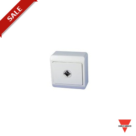
BOW-LUX CARLO GAVAZZI Parametri selezionati Altro INFO1 Sensore LUX INFO2 Opus INFO3 Alimentato dal Bus INFO..
BOW-LUX
CARLO GAVAZZI
Parametri selezionati Altro INFO1 Sensore LUX INFO2 Opus INFO3 Alimentato dal Bus INFO4 Sensore di LUX per conrollo costante del livello lluce in collegamento con f BH4-DD10V2-230
Home > CARLO GAVAZZI
* Prodotto nuovo nel suo imballaggio d'origine con tutte le garanzie e certificazioni de CARLO GAVAZZI
Dettagli
▲Light Sensor
BOW-LUX
For daylight regulation applications
Supplied by smart-house
For ceiling mounting
Channel coding by BGP-COD-BAT OPUS housing
INPUT SPECIFICATIONS
Signal input Visible light
Spectral range 330 – 720 nm
Infrared rejection filter
Spectral peak 580 nm
Viewing angle 26°
Optical range 0 – 100 Lux
400 – 500 Lux at table height is approximately
25 Lux measured by the sensor, depending on the reflection factor and the distance
Response time 9 cycles
≤ 1224 ms @ 128 channels
GENERAL SPECIFICATIONS
Power-on delay ≤ 1 s
Environment
Degree of protection IP 20
Pollution degree 3 (IEC 60664)
Operating temperature 0 to 50 °C (32 to 122°F)
Storage temperature -20 to 85°C (-4 to 185°F)
Humidity (non condensing) ≤ 85%
Material OPUS 66 housing
66 x 66 x 35 mm
Weight 60 g
Standards IEC 60669, EN 55022/
EN 50081-1 and EN 55024/ EN 50082-1
SUPPLY SPECIFICATIONS
Power supply Supplied by smart-house
Current consumption ≤ 4 mA
TYPE SELECTION
Supply Color Ordering no.
By smart-house White BOW-LUX
MODE OF OPERATION
Coding
With the BGP-COD-BAT program- ming unit, each channel can be assigned any address between A1 and P8 via the programming con- nection on the PCB. For connection of BGP-COD-BAT to a module, the cable GAP-TPH-CAB must be used. The allocation of the channels is as follows:
Channel Default Description address
Sync. input
signal. It is retained permanently, but may be overwritten at any time.
Functions and programming
For transmission of light levels from the light sensors, channel 2 (A2) is used as output for serial data. Channel 1 (A7) is also used for transmitting data. The channel is used as an input for synchronizing the serial data. In the configuration software for the Controller, the channel must be selected as a "Daylight sync." channel. The Controller will then automatically generate the sync. signal used for
the controller and the light sensor.
Mounting
The sensor must be mounted in the ceiling and directed towards the floor. It is important to place the sensor where it will not be hit by any direct sunlight during the day. It is also important that the sensor is placed correctly in the room. Since it can be difficult to find the ideal place the first time, it may be nec- essary to change the placement of the sensor if the regulation during the day is not optimum.
As a starting point, the sensor should be placed in the area, where the sunlight contributes least to the
total light in the room. This means
is regulated by a sensor placed within this area, while an area away from the windows is regulat- ed by its own sensor. In this area, a larger amount of lighting will usual- ly be needed to maintain a homo- geneous light level in the room.
The sensors must be placed so that they have a free view. This means that no large objects, like big flowers, shelves etc. must be placed under the sensors. In addition, it is important that no kind of up-light is placed near the sen- sors, or that the area around the sensor is not lit up with for
example table lamps, which are not
1 B1
for light
level data
Only one channel in the smart- house system needs to be con- figured as sync. channel, independ-
that in most cases it will be recom- mended to place the sensor at the back of the room in relation to the
connected to the Daylight con- troller.
2 A2 Light level
output
The coding of the sensor can be carried out without smart-house
ently of the number of light con- trollers and light sensors. All sync. channels of the modules just have to be configured to the same chan- nel selected in the Controller.
windows.
It is advantageous to split up a room in several light groups: one area (light group) close to the windows
Specifications are subject to change without notice (01.12.2009) - A product of the CARLO GAVAZZI Group
Datasheet - PDF
▲Recensioni: (0) ▲
Nessun commento per il momento.
| Valutazione: |


|
| Nome: | |
| Email: | |
| Titolo: | |
| Testo: | |
| Mi consiglia questo prodotto da acquistare? | |
|
|
|
| Inserisci recensione | |
Tutti i feedback che riceviamo dagli elementi che offriamo sono reali e verificati. Un piccolo gesto, ma di grande valore. Quindi grazie per quel minuto si spende in noi lasciare il vostro parere e punteggio sui prodotti, perché ci aiuta a continuare a migliorare e di offrire ancora maggiore qualità del servizio.


