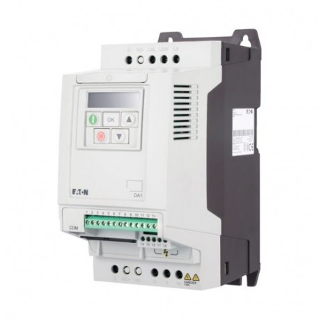
DA1-345D8FB-A20C 169051 EATON ELECTRIC PowerXL Drive Série DA1 Agrandir l'image
Les images sont à titre illustratif. Svp, révisez la fiche technique.

DA1-345D8FB-A20C 169051 EATON ELECTRIC PowerXL Drive Série DA1

DA1-345D8FB-A20C

169051

EATON-MOELLER

PowerXL Drive - Série DA1

DA1-345D8FB-A20C

Eaton DA1 Variable frequency drive, 400 V AC, 3-phase, 5.8 A, 2.2 kW, IP20/NEMA 0, Radio interference suppression filter, 7-digital display assembly

Plus de détails


Appareillage industriel basse tension > Convertisseur de fréquences el 1 kV

Convertisseurs de fréquence Power XL

* Produit neuf dans son emballage d'origine avec toutes les garanties et les certifications émises par EATON-MOELLER

Prix total: $612.38
Prix unitaire: $612.38

Quantité Prix
1+$612.38
2+$612.38
*Ce prix est par unité et montre la valeur nette (excluant les taxes indirectes le cas échéant) .

Si notre prix n'est pas le meilleur, demandez-nous un devis. Demander un devis

Les plus vendus

En savoir plus


Spécifications générales

Product Name
Eaton DA1 Variable frequency drive
Catalog Number
169051
Model Code
DA1-345D8FB-A20C
EAN
4015081655427
Product Length/Depth
186 mm
Product Height
231 mm
Product Width
107 mm
Product Weight
1.8 kg
Certifications
Safety: EN 61800-5-1: 2003
UL
CSA-C22.2 No. 14
UL report applies to both US and Canada
RoHS, ISO 9001
UkrSEPRO
UL 508C
IEC/EN61800-3
RCM
UL File No.: E172143
IEC/EN 61800-3
EAC
CE
Certified by UL for use in Canada
IEC/EN61800-5
Specification for general requirements: IEC/EN 61800-2
UL Category Control No.: NMMS, NMMS7
CUL
Catalog Notes
The brake resistors are assigned based on the maximum rated power of the variable frequency drive. Additional brake resistors and designs (e.g. different duty cycles) are available upon request.

Climatic environmental conditions

Ambient operating temperature - min
-10 °C
Altitude
Max. 4000 m
Max. 1000 m
Above 1000 m with 1 % derating per 100 m
Ambient operating temperature - max
50 °C
Ambient operating temperature at 150% overload - min
-10 °C
Ambient operating temperature at 150% overload - max
50 °C
Ambient storage temperature - min
-40 °C
Ambient storage temperature - max
60 °C
Climatic proofing
< 95 average relative humidity (RH), no condensation, no corrosion

Main circuit

Efficiency
95.4 % (η)
Heat dissipation at current/speed
35 W at 25% current and 0% speed
38 W at 25% current and 50% speed
43 W at 50% current and 0% speed
47 W at 50% current and 50% speed
51 W at 100% current and 0% speed
57 W at 50% current and 90% speed
66 W at 100% current and 50% speed
81 W at 100% current and 90% speed
Input current ILN at 150% overload
7.5 A
Leakage current at ground IPE - max
4.65 mA
Mains switch-on frequency
Maximum of one time every 30 seconds
Mains voltage - min
380 V
Mains voltage - max
480 V
Operating mode
U/f control
Optional: Vector control with feedback (CLV)
Sensorless vector control (SLV)
Speed control with slip compensation
Output frequency - min
0 Hz
Output frequency - max
500 Hz
Output voltage (U2)
400 V AC, 3-phase
480 V AC, 3-phase
Overload current IL at 150% overload
8.7 A
Rated control supply voltage
10 V DC (Us, max. 10 mA)
Rated frequency - min
48 Hz
Rated frequency - max
62 Hz
Rated operational current (Ie) at 150% overload
5.8 A
Rated operational power at 380/400 V, 50 Hz, 3-phase
2.2 kW
Rated operational voltage
400 V AC, 3-phase
480 V AC, 3-phase
Resolution
0.1 Hz (Frequency resolution, setpoint value)
Short-circuit protection rating
10 A, UL (Class CC or J), Safety device (fuse or miniature circuit-breaker), Power Wiring
Starting current - max
200 %, IH, max. starting current (High Overload), for 4 seconds every 40 seconds, Power section
Supply frequency
50/60 Hz
Switching frequency
8 kHz, 4 - 32 kHz adjustable (audible), fPWM, Power section, Main circuit
System configuration type
AC supply systems with earthed center point
Voltage rating - max
480 VAC

Motor rating

Assigned motor current IM at 400 V, 50 Hz, 150% overload
5 A
Assigned motor current IM at 440 - 480 V, 60 Hz, 150% overload
4.8 A
Assigned motor power at 460/480 V, 60 Hz, 3-phase
3 HP

Apparent power

Apparent power at 400 V
4.02 kVA
Apparent power at 480 V
4.82 kVA

Braking function

Braking resistance
150 Ω
Braking torque
Max. 30 % MN, Standard - Main circuit
Max. 100 % of rated operational current Ie with external braking resistor - Main circuit
Max. 100 % of rated operational current Ie, variable, DC - Main circuit
Switch-on threshold for the braking transistor
780 VDC

Control circuit

Number of inputs (analog)
2
Number of inputs (digital)
5
Number of outputs (analog)
2
Number of outputs (digital)
2
Number of relay outputs
2 (parameterizable, 1 N/O and 1 changeover contact, 6 A (250 V, AC-1) / 5 A (30 V, DC-1))
Rated control voltage (Uc)
24 V DC (external, max. 100 mA)

Design verification

Equipment heat dissipation, current-dependent Pvid
101.2 W
Heat dissipation capacity Pdiss
0 W
Heat dissipation per pole, current-dependent Pvid
0 W
Rated operational current for specified heat dissipation (In)
5.8 A
Static heat dissipation, non-current-dependent Pvs
0 W
10.2.2 Corrosion resistance
Meets the product standard's requirements.
10.2.3.1 Verification of thermal stability of enclosures
Meets the product standard's requirements.
10.2.3.2 Verification of resistance of insulating materials to normal heat
Meets the product standard's requirements.
10.2.3.3 Resist. of insul. mat. to abnormal heat/fire by internal elect. effects
Meets the product standard's requirements.
10.2.4 Resistance to ultra-violet (UV) radiation
Meets the product standard's requirements.
10.2.5 Lifting
Does not apply, since the entire switchgear needs to be evaluated.
10.2.6 Mechanical impact
Does not apply, since the entire switchgear needs to be evaluated.
10.2.7 Inscriptions
Meets the product standard's requirements.
10.3 Degree of protection of assemblies
Does not apply, since the entire switchgear needs to be evaluated.
10.4 Clearances and creepage distances
Meets the product standard's requirements.
10.6 Incorporation of switching devices and components
Does not apply, since the entire switchgear needs to be evaluated.
10.7 Internal electrical circuits and connections
Is the panel builder's responsibility.
10.8 Connections for external conductors
Is the panel builder's responsibility.
10.9.2 Power-frequency electric strength
Is the panel builder's responsibility.
10.9.3 Impulse withstand voltage
Is the panel builder's responsibility.
10.9.4 Testing of enclosures made of insulating material
Is the panel builder's responsibility.
10.10 Temperature rise
The panel builder is responsible for the temperature rise calculation. Eaton will provide heat dissipation data for the devices.
10.11 Short-circuit rating
Is the panel builder's responsibility. The specifications for the switchgear must be observed.
10.12 Electromagnetic compatibility
Is the panel builder's responsibility. The specifications for the switchgear must be observed.
10.13 Mechanical function
The device meets the requirements, provided the information in the instruction leaflet (IL) is observed.

Datasheet - PDF

Commentaires: (0)

Aucun commentaire sur le produit encore.

Écrire commentaire
Sous forme de peau
Score:
Nom:
Email:
Titre:
Commentaire:
  Captcha
  Écrire commentaire

Toutes les évaluations que nous recevons des articles que nous proposons sont réels et vérifiés. Un petit geste, mais très précieux. Je vous remercie pour cette minute que vous passez à nous laisser votre avis et note sur les produits, car il nous aide à continuer à améliorer et à offrir encore plus la qualité de service.