No products
Product successfully added to your shopping cart
 View larger
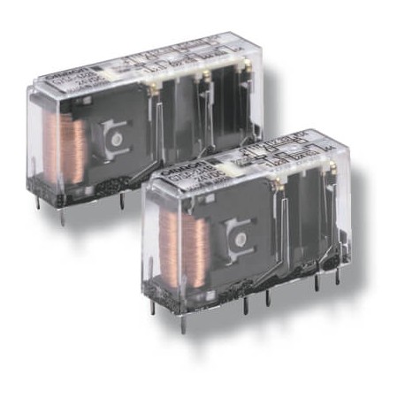
P7SA-14F 377194 OMRON Base G7SA 6polos DIN Rail Screw
P7SA-14F
377194
P7SA14F
OMRON
Base G7SA 6polos DIN Rail Screw
Safety > G7S
* Brand new product in its original packaging covered by the warranties and certifications provided by OMRON
More info
▲Relays with forcibly guided contacts
The slim G7SA relay family with forcibly guided contacts is available as a four or six-pole type in various contact combinations and offers reinforced insulation. Terminals are arranged for easy PCB layout. It can be soldered directly to a PCB or used together with the P7SA sockets.
- Forcibly guided contacts
- Conforms to EN 50205
- 6 A at 240 VAC and 6A at 24 VDC for resistive loads
- Reinforced insulation between inputs, outputs and poles
- 4- and 6-pole relays available
- Sockets available with Push-In technology
Ordering information
Relays with forcibly guided contacts
24 VDC1 | |||||
Sockets
Specifications
Coil
Note:Refer to datasheet for details
Contacts
Relays with forcibly guided contacts
100 mΩ max. (The contact resistance was measured with 1 A at 5 VDC using the voltage-drop method.) | ||
Operating time2 | ||
Response time1 | 10 ms max. | |
Release time1 | ||
100 MΩ min. (at 500 VDC) (The insulation resistance was measured with a 500 VDC megger at the same places that the dielectric strength was | ||
| Between coil contacts/different poles: 4,000 VAC, 50/60 Hz for 1 min Between contacts of same polarity: 1,500 VAC, 50/60 Hz for 1 min | ||
10,000,000 operations min. (at approx. 36,000 operations/hr) | ||
100,000 operations min. (at the rated load and approx. 1,800 operations/hr) | ||
Min. permissible load5 | ||
Ambient temperature6 | ||
Note:The values listed above are initial values.
Please check Omron in the Internet for updated information on product reliability data and the SISTEMA libraries: http://industrial.omron.eu/safety
Datasheet - PDF
▲| Title: | Size: | Type: |
|---|---|---|
| P7SA-14F P7SA14F 377194 | 240 Kbytes |
 |
| P7SA-14F P7SA14F 377194 j120_g7sa_relays_with_forcibly_guided_contacts_datasheet_en.pdf | 3 Mbytes |
 |
Reviews (0) ▲
No customer reviews for the moment.
| Rating: |


|
| Name: | |
| Email: | |
| Subject: | |
| Text: | |
| Do you recommend this product to buy? | |
|
|
|
| Add review | |
All ratings we receive from the items we offer are real and verified. A small gesture, but a lot of value. That's why we thank you for that minute you invest in leaving us your opinion and qualification about the products, because it helps us to continue improving and to offer you a service of even higher quality.


