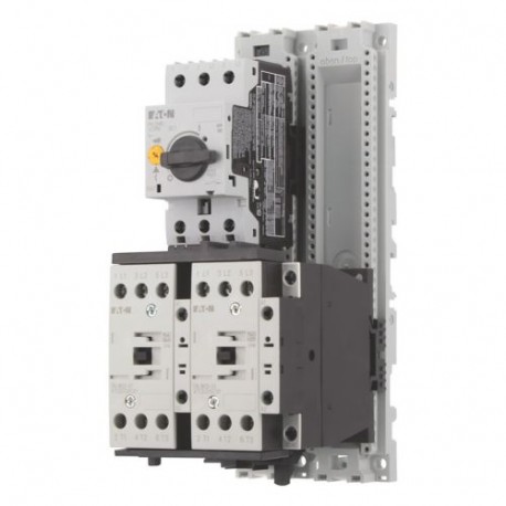
MSC-R-32-M32(24VDC) 283206 EATON ELECTRIC Reversing starter, 3p, 15kW/400V/AC3, 50kA View larger
Images are for illustrative purposes only. Please refer to data sheet for details.

MSC-R-32-M32(24VDC) 283206 EATON ELECTRIC Reversing starter, 3p, 15kW/400V/AC3, 50kA

MSC-R-32-M32(24VDC)

283206

EATON-MOELLER

Reversing starter, 3p, 15kW/400V/AC3, 50kA

MSC-R-32-M32(24VDC)

Reversing starter, 380 V 400 V 415 V: 15 kW, Ir= 25 - 32 A, 24 V DC, DC voltage

More details


Low-voltage industrial components > Motor starter/Motor starter combination

Circuit Breakers PKZ

* Brand new product in its original packaging covered by the warranties and certifications provided by EATON-MOELLER

Total price: $373.81
Unit price: $373.81

*This price is per unit and is the net value (not including taxes if applicable).

If our price is not the best, please ask us for a quote. Ask for a quotation

More info


Reversing starter, 380 V 400 V 415 V: 15 kW, Ir= 25 - 32 A, 24 V DC, DC voltage
Reversing starter, Basic device: MSC, Notes: Also suitable for motors with efficiency class IE3., IE3-ready devices are identified by the logo on their packaging., Motor ratings Motor rating AC-3 380 V 400 V 415 V: P= 15 kW, Setting range of overload releases: Ir= 25 - 32 A, Coordination: Type of coordination “1”, Type of coordination “2”, Actuating voltage: 24 V DC, DC voltage, Standards: UL 508 (on request), CSA C 22.2 No. 14 (on request)

Delivery program

Basic function
Reversing starters (completedevices)
Basic device
MSC
0000SPC-571
Notes
Also suitable for motors with efficiency class IE3.
IE3-ready devices are identified by the logo on their packaging.
Connection to SmartWire-DT
no
Motor ratings
Motor rating [P]AC-3380 V 400 V 415 V [P]
15 kW
Rated operational currentAC-3380 V 400 V 415 V [Ie]
29.3 A
Rated short-circuit current 380 - 415 V [Iq]
50 kA
Setting range
Setting range of overload releases[Ir]
25 - 32 A
Coordination
Type of coordination “1”
Type of coordination “2”
Contact sequence
121S030
Actuating voltage
24 V DC
DC voltage
Motor-protective circuit-breakers
PKZM0-32 Type
Contactor
DILM32-01(...) Part no.
DOL starter wiring set

Mechanical connection element and electrical electric contact module
PKZM0-XRM32 Type
Notes

The reversing starter (complete unit) consists of a PKZM0 motor-protective circuit-breaker and two DILM contactors.

With the adapter-less top-hat rail mounting of starters up to 12 A, only the motor-protective circuit-breaker on the top-hat rail requires an adapter. The contactors are provided with mechanical support via a mechanical connection element.

Control wire guide with max. 6 conductors up to 2.5mm external diameter or 4 conductors up to 3.5mm external diameter.

From 16 A, the motor-protective circuit-breakers and contactors are mounted on the top-hat rail adapter plate.

The connection of the main circuit between PKZ and contactor is established with electrical contact modules.

Complete units with mechanical interlock, starters up to 12 A also feature electrical interlock.

When using the auxiliary contacts DILA‐XHIT… (→ 101042) the plug-in electrical connector can be removed without the removal of the front mounting auxiliary contact.

For further informationPage
Technical data PKZM0PKZM0
Accessories PKZ→ 072896
Technical data DILMDILM
Further actuating voltages→ 276537
DILM accessories→ 281199

Technical data

General
Standards

UL 508 (on request)
CSA C 22.2 No. 14 (on request)
Mounting position
2115DRW-6
Altitude
Max. 2000 m
Ambient temperature
-25 - +55
Main conducting paths
Rated impulse withstand voltage [Uimp]
6000 V AC
Overvoltage category/pollution degree
III/3
Rated operational voltage [Ue]
230 - 415 V
Rated operational currentOpen, 3-pole: 50 – 60 Hz380 V 400 V [Ie]
32 A
Additional technical data
Motor protective circuit breaker PKZM0, PKE
PKZM0 motor-protective circuit-breakers, see motor-protective circuit-breakers/PKZM0 product group
DILM contactors, see contactor product group
DILET timing relay, ETR, see contactors, electronic timing relays product group
Power consumption
DC operated [Sealing]
0.5 W
Rating data for approved types
Auxiliary contactsPilot DutyAC operated
A600
Auxiliary contactsPilot DutyDC operated
P300
Auxiliary contactsGeneral UseAC
600 V
Auxiliary contactsGeneral UseAC
15 A
Auxiliary contactsGeneral UseDC
250 V
Auxiliary contactsGeneral UseDC
1 A

Design verification as per IEC/EN 61439

Technical data for design verification
Rated operational current for specified heat dissipation [In]
32 A
Heat dissipation per pole, current-dependent [Pvid]
6.5 W
Equipment heat dissipation, current-dependent [Pvid]
19.5 W
Static heat dissipation, non-current-dependent [Pvs]
0.9 W
Heat dissipation capacity [Pdiss]
0 W
Operating ambient temperature min.
-25 °C
Operating ambient temperature max.
+55 °C
IEC/EN 61439 design verification
10.2 Strength of materials and parts10.2.2 Corrosion resistance
Meets the product standard's requirements.
10.2 Strength of materials and parts10.2.3.1 Verification of thermal stability of enclosures
Meets the product standard's requirements.
10.2 Strength of materials and parts10.2.3.2 Verification of resistance of insulating materials to normal heat
Meets the product standard's requirements.
10.2 Strength of materials and parts10.2.3.3 Verification of resistance of insulating materials to abnormal heat and fire due to internal electric effects
Meets the product standard's requirements.
10.2 Strength of materials and parts10.2.4 Resistance to ultra-violet (UV) radiation
Meets the product standard's requirements.
10.2 Strength of materials and parts10.2.5 Lifting
Does not apply, since the entire switchgear needs to be evaluated.
10.2 Strength of materials and parts10.2.6 Mechanical impact
Does not apply, since the entire switchgear needs to be evaluated.
10.2 Strength of materials and parts10.2.7 Inscriptions
Meets the product standard's requirements.
10.3 Degree of protection of ASSEMBLIES
Does not apply, since the entire switchgear needs to be evaluated.
10.4 Clearances and creepage distances
Meets the product standard's requirements.
10.5 Protection against electric shock
Does not apply, since the entire switchgear needs to be evaluated.
10.6 Incorporation of switching devices and components
Does not apply, since the entire switchgear needs to be evaluated.
10.7 Internal electrical circuits and connections
Is the panel builder's responsibility.
10.8 Connections for external conductors
Is the panel builder's responsibility.
10.9 Insulation properties10.9.2 Power-frequency electric strength
Is the panel builder's responsibility.
10.9 Insulation properties10.9.3 Impulse withstand voltage
Is the panel builder's responsibility.
10.9 Insulation properties10.9.4 Testing of enclosures made of insulating material
Is the panel builder's responsibility.
10.10 Temperature rise
The panel builder is responsible for the temperature rise calculation. Eaton will provide heat dissipation data for the devices.
10.11 Short-circuit rating
Is the panel builder's responsibility. The specifications for the switchgear must be observed.
10.12 Electromagnetic compatibility
Is the panel builder's responsibility. The specifications for the switchgear must be observed.
10.13 Mechanical function
The device meets the requirements, provided the information in the instruction leaflet (IL) is observed.

Technical data ETIM 7.0

Low-voltage industrial components (EG000017) / Motor starter/Motor starter combination (EC001037)
Electric engineering, automation, process control engineering / Low-voltage switch technology / Load breakout, motor breakout / Motor starter combination ([email protected] [AJZ718013])
Kind of motor starter
Reversing starter
With short-circuit release
Yes
Rated control supply voltage Us at AC 50HZ
0 - 0 V
Rated control supply voltage Us at AC 60HZ
0 - 0 V
Rated control supply voltage Us at DC
24 - 24 V
Voltage type for actuating
DC
Rated operation power at AC-3, 230 V, 3-phase
7.5 kW
Rated operation power at AC-3, 400 V
15 kW
Rated power, 460 V, 60 Hz, 3-phase
0 kW
Rated power, 575 V, 60 Hz, 3-phase
0 kW
Rated operation current Ie
29.3 A
Rated operation current at AC-3, 400 V
32 A
Overload release current setting
25 - 32 A
Rated conditional short-circuit current, type 1, 480 Y/277 V
0 A
Rated conditional short-circuit current, type 1, 600 Y/347 V
0 A
Rated conditional short-circuit current, type 2, 230 V
50000 A
Rated conditional short-circuit current, type 2, 400 V
50000 A
Number of auxiliary contacts as normally open contact
0
Number of auxiliary contacts as normally closed contact
0
Ambient temperature, upper operating limit
60 °C
Temperature compensated overload protection
Yes
Release class
CLASS 10
Type of electrical connection of main circuit
Screw connection
Type of electrical connection for auxiliary- and control current circuit
Screw connection
Rail mounting possible
Yes
With transformer
No
Number of command positions
0
Suitable for emergency stop
No
Coordination class according to IEC 60947-4-3
Class 2
Number of indicator lights
0
External reset possible
No
With fuse
No
Degree of protection (IP)
IP00
Degree of protection (NEMA)
Other
Supporting protocol for TCP/IP
No
Supporting protocol for PROFIBUS
No
Supporting protocol for CAN
No
Supporting protocol for INTERBUS
No
Supporting protocol for ASI
No
Supporting protocol for MODBUS
No
Supporting protocol for Data-Highway
No
Supporting protocol for DeviceNet
No
Supporting protocol for SUCONET
No
Supporting protocol for LON
No
Supporting protocol for PROFINET IO
No
Supporting protocol for PROFINET CBA
No
Supporting protocol for SERCOS
No
Supporting protocol for Foundation Fieldbus
No
Supporting protocol for EtherNet/IP
No
Supporting protocol for AS-Interface Safety at Work
No
Supporting protocol for DeviceNet Safety
No
Supporting protocol for INTERBUS-Safety
No
Supporting protocol for PROFIsafe
No
Supporting protocol for SafetyBUS p
No
Supporting protocol for other bus systems
No
Width
90 mm
Height
228 mm
Depth
123.4 mm

Approvals

Product Standards
UL60947-4-1A; CSA-C22.2 No. 14-10; IEC60947-4-1; CE marking
UL File No.
E123500
UL Category Control No.
NKJH
CSA File No.
12528
CSA Class No.
3211-24
North America Certification
UL listed, CSA certified
Specially designed for North America
No

Dimensions

2115DIM-4
MSC-R-…-M17[…32]…

Datasheet - PDF

Reviews (0)

No customer reviews for the moment.

Add Review
hide form
Rating:
Name:
Email:
Subject:
Text:
  Captcha
  Add review

All ratings we receive from the items we offer are real and verified. A small gesture, but a lot of value. That's why we thank you for that minute you invest in leaving us your opinion and qualification about the products, because it helps us to continue improving and to offer you a service of even higher quality.