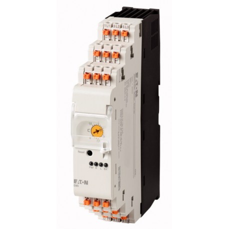
EMS-RO-T-2,4-24VDC 170101 EMS-RO-T-2P4-24VDC EATON ELECTRIC 170101 EMS-RO-T-2,4-24VDC View larger
Images are for illustrative purposes only. Please refer to data sheet for details.

EMS-RO-T-2,4-24VDC 170101 EMS-RO-T-2P4-24VDC EATON ELECTRIC 170101 EMS-RO-T-2,4-24VDC

EMS-RO-T-2,4-24VDC

170101

EMS-RO-T-2P4-24VDC

EATON-MOELLER

170101 EMS-RO-T-2,4-24VDC

Reversing starter, 24 V DC, 0,18 - 2,4 A, Push in terminals, PTB 13 ATEX 3003

More details


Low-voltage industrial components > Motor starter/Motor starter combination

Standard Soft Starters

* Brand new product in its original packaging covered by the warranties and certifications provided by EATON-MOELLER

* This article may be obsolete. Ask for a quotation and we will check if there are any units available. If not, one of our technicians will look for an alternative solution.

If our price is not the best, please ask us for a quote. Ask for a quotation

More info


EL-Nummer (Norway)
4137397
Reversing starter, 24 V DC, 0,18 - 2,4 A, Push in terminals, PTB 13 ATEX 3003
Reversing starter, Actuating voltage: 24 V DC, Standards: IEC/EN 60947-4-2, UL508

Delivery program

This item is only available for a limited time. Replacement item: Art. no. 192392, Type: EMS2-RO-T-2.4-24VDC
Product range
Electronic motor starter
Basic function
Reversing starters (completedevices)
Description
DOL starting
Reversing start
Motor protection
Circuit design: safety output stage with bypass, three-phase disconnect.
Conformity, Approval
Explosion protection (according to ATEX 94/9/EC)
II (2) G [Ex e] [Ex d] [Ex px]
II (2) D [Ex t] [Ex p]
EC-prototype test certification
PTB 13 ATEX 3003
Motor ratings
Max. rating for three-phase motors, 50 - 60 HzAC-53a380 V 400 V 415 V [P]
0.06 - 0.75 kW
Setting range of overload releases[Ir]
0,18 - 2,4 A_x
Actuating voltage
24 V DC
Connection technique
Push in terminals
Connection to SmartWire-DT
no

Technical data

General
Standards
IEC/EN 60947-4-2
UL508
DimensionsWidth
30 mm
DimensionsHeight
157 mm
DimensionsDepth
123.5 mm
Weight
0.3 kg
Mounting
Top-hat rail IEC/EN 60715, 35 mm
Protection type (IEC/EN 60529, EN50178, VBG 4)
IP20
Mounting position
Vertical
Motor feeder at bottom
Lifespan, electrical [Operations]
3 x 10⁷
Max. switching frequency
7200 (pulse pause time 50:50) Operations/h
Terminal capacitySolid
1 x (0.75 - 2.5)
1 x AWG20 - 14 mm2
Terminal capacityflexible, with ferrule
2 x (0,75 - 2,5)
1 x AWG20 - 14 mm2
Terminal capacityNotes
Minimum length 10 mm.
Terminal capacityflexible, with twin ferrule
2 x (0,75 - 1,5)
2 x AWG20 - 16 mm2
Terminal capacityNotes
Minimum length 10 mm.
Climatic environmental conditions
Operating ambient temperature
-25 - +60, in accordance with IEC 60068-2-1 °C
Condensation
Take appropriate measures to prevent condensation
Storage [ϑ]
-40 - +80 °C
Main conducting paths
Rated impulse withstand voltage [Uimp]
6000 V AC
Overvoltage category/pollution degree
III/2
Rated operational voltage [Ue]
42 - 550 V
Rated operational currentAC-51 [Ie]
0.15 - 2.40 A
Rated operational currentAC-53a [Ie]
0.15 - 2.4 A
Heat dissipation [PV]
1.1 - 3.3 W
Static heat dissipation, non-current-dependent [Pvs]
1 W
Basic insulation to IEC/EN60947-1Between supply, control, and switching voltages
500 V AC
Basic insulation to IEC/EN60947-1between feedback signal output and switch voltage
500 V AC
Safe isolation to IEC/EN60947-1Between supply, control, and switching voltages
≦ 300 V AC
Safe isolation to IEC/EN60947-1between feedback signal output and switch voltage
≦ 300 V AC
Safe isolation to EN 50178Between supply, control, and switching voltages
500 V AC
Safe isolation to EN 50178between feedback signal output and switch voltage
500 V AC
Current measurementSetting range of overload releases[Ir]
0,18 - 2,4 A_x
Current measurementRelease class
10 CLASS
Current measurementRecovery time [tW]
2 (manual startup)
20 (automatic restart) min.
Current measurementBalance monitoringMagnitude Imax> Irated((Imax- Imin)/Imax)
If ≧ 33, pick-up time of 120 s
If ≧ 67, pick-up time of 1.8 s %
Current measurementBalance monitoringMagnitude Imax< Irated((Imax- Imin)/Irated)
If ≧ 33, pick-up time of 120 s
If ≧ 67, pick-up time of 1.8 s %
Short-circuit ratingType “1” coordinationShort-circuit protective device
50 kA, 500 V AC: Fuse 16 A gG/gL
50 kA, 415 V AC: PKM0-4
15 kA, 415 V AC: PKM0-6,3
Control section
Input dataSupply voltage [UAUX]
A1 - A2: 24 (-20 - +25 %) V DC
Input dataResidual ripple on the input voltage
≦ 5 %
Input dataInput current
40 mA
Input dataNote on input current
without feedback signal
Actuating circuit (ON, L, R)Switching level "Low"
-3 - +9.6 V DC V
Actuating circuit (ON, L, R)Switching level "confirm Off"
< 5 V DC V
Actuating circuit (ON, L, R)Switching level "High"
19.2 - 30 V DC V
Actuating circuit (ON, L, R)Input current
5 mA
Feedback outputsNotes
Contacts 95, 96 or 98
Feedback outputsContactsCO = changeover
1 CO
Feedback outputsRated operational voltage [Ue]
250 V AC/DC
Feedback outputsRated operational currentAC-15230 V [Ie]
3 A
Feedback outputsRated operational currentDC-1324 V [Ie]
2 A
Electromagnetic compatibility (EMC)
Electrostatic discharge (ESD)applied standard
IEC/EN 61000-4-2, Level 3
Electrostatic discharge (ESD)Air discharge
8 kV
Electrostatic discharge (ESD)Contact discharge
6 kV
Electromagnetic fields (RFI)applied standard
IEC/EN 61000-4-3
Electromagnetic fields (RFI)
800 - 1000 MHz: 10
1.4 - 2 GHz: 10
2.0 - 2.7 GHz: 3 V/m
Radio interference suppression
EN 55011, Class A (emitted interference, line-conducted)
EN 61000-6-3, Class A (emitted interference, radiated)
Note on use
This product is designed for operation in industrial environments (environment 2). The use in residential environments (environment 1) could cause electrical interference so that addition suppression must be planned.
Burst
2
IEC/EN 61000-4-4, level 3 kV
power pulses (Surge)
1 kV (symmetrical)
2 kV (asymmetrical)
according to IEC/EN 61000-4-5
Immunity to line-conducted interference to (IEC/EN 61000-4-6)
10 V
Technical safety parameters:
Notes
motor protection
Ambient temperature
40 °C
Values according to EN ISO 13849-1MTTFd[Years]
316
Values according to IEC 62061
λsd [FIT]: 0
λsu [FIT]: 1731
λdd [FIT]: 314
λdu [FIT]: 47,2
SFF [%]: 97,7
DC [%]: 86,9
SIL: 2
Notes
motor protection

Design verification as per IEC/EN 61439

Technical data for design verification
Rated operational current for specified heat dissipation [In]
2.4 A
Heat dissipation per pole, current-dependent [Pvid]
0.7 W
Equipment heat dissipation, current-dependent [Pvid]
2 W
Static heat dissipation, non-current-dependent [Pvs]
1 W
Heat dissipation capacity [Pdiss]
0 W
Operating ambient temperature min.
-25 °C
Operating ambient temperature max.
+60 °C
IEC/EN 61439 design verification
10.2 Strength of materials and parts10.2.2 Corrosion resistance
Meets the product standard's requirements.
10.2 Strength of materials and parts10.2.3.1 Verification of thermal stability of enclosures
Meets the product standard's requirements.
10.2 Strength of materials and parts10.2.3.2 Verification of resistance of insulating materials to normal heat
Meets the product standard's requirements.
10.2 Strength of materials and parts10.2.3.3 Verification of resistance of insulating materials to abnormal heat and fire due to internal electric effects
Meets the product standard's requirements.
10.2 Strength of materials and parts10.2.4 Resistance to ultra-violet (UV) radiation
Meets the product standard's requirements.
10.2 Strength of materials and parts10.2.5 Lifting
Does not apply, since the entire switchgear needs to be evaluated.
10.2 Strength of materials and parts10.2.6 Mechanical impact
Does not apply, since the entire switchgear needs to be evaluated.
10.2 Strength of materials and parts10.2.7 Inscriptions
Meets the product standard's requirements.
10.3 Degree of protection of ASSEMBLIES
Does not apply, since the entire switchgear needs to be evaluated.
10.4 Clearances and creepage distances
Meets the product standard's requirements.
10.5 Protection against electric shock
Does not apply, since the entire switchgear needs to be evaluated.
10.6 Incorporation of switching devices and components
Does not apply, since the entire switchgear needs to be evaluated.
10.7 Internal electrical circuits and connections
Is the panel builder's responsibility.
10.8 Connections for external conductors
Is the panel builder's responsibility.
10.9 Insulation properties10.9.2 Power-frequency electric strength
Is the panel builder's responsibility.
10.9 Insulation properties10.9.3 Impulse withstand voltage
Is the panel builder's responsibility.
10.9 Insulation properties10.9.4 Testing of enclosures made of insulating material
Is the panel builder's responsibility.
10.10 Temperature rise
The panel builder is responsible for the temperature rise calculation. Eaton will provide heat dissipation data for the devices.
10.11 Short-circuit rating
Is the panel builder's responsibility. The specifications for the switchgear must be observed.
10.12 Electromagnetic compatibility
Is the panel builder's responsibility. The specifications for the switchgear must be observed.
10.13 Mechanical function
The device meets the requirements, provided the information in the instruction leaflet (IL) is observed.

Technical data ETIM 7.0

Low-voltage industrial components (EG000017) / Motor starter/Motor starter combination (EC001037)
Electric engineering, automation, process control engineering / Low-voltage switch technology / Load breakout, motor breakout / Motor starter combination ([email protected] [AJZ718013])
Kind of motor starter
Reversing starter
With short-circuit release
No
Rated control supply voltage Us at AC 50HZ
0 - 0 V
Rated control supply voltage Us at AC 60HZ
0 - 0 V
Rated control supply voltage Us at DC
24 - 24 V
Voltage type for actuating
DC
Rated operation power at AC-3, 230 V, 3-phase
0.37 kW
Rated operation power at AC-3, 400 V
0.75 kW
Rated power, 460 V, 60 Hz, 3-phase
0.736 kW
Rated power, 575 V, 60 Hz, 3-phase
0 kW
Rated operation current Ie
2.4 A
Rated operation current at AC-3, 400 V
2.4 A
Overload release current setting
0.18 - 2.4 A
Rated conditional short-circuit current, type 1, 480 Y/277 V
0 A
Rated conditional short-circuit current, type 1, 600 Y/347 V
0 A
Rated conditional short-circuit current, type 2, 230 V
0 A
Rated conditional short-circuit current, type 2, 400 V
0 A
Number of auxiliary contacts as normally open contact
1
Number of auxiliary contacts as normally closed contact
1
Ambient temperature, upper operating limit
60 °C
Temperature compensated overload protection
Yes
Release class
CLASS 10
Type of electrical connection of main circuit
Spring clamp connection
Type of electrical connection for auxiliary- and control current circuit
Spring clamp connection
Rail mounting possible
Yes
With transformer
No
Number of command positions
0
Suitable for emergency stop
No
Coordination class according to IEC 60947-4-3
Class 1
Number of indicator lights
4
External reset possible
Yes
With fuse
No
Degree of protection (IP)
IP20
Degree of protection (NEMA)
Other
Supporting protocol for TCP/IP
No
Supporting protocol for PROFIBUS
No
Supporting protocol for CAN
No
Supporting protocol for INTERBUS
No
Supporting protocol for ASI
No
Supporting protocol for MODBUS
No
Supporting protocol for Data-Highway
No
Supporting protocol for DeviceNet
No
Supporting protocol for SUCONET
No
Supporting protocol for LON
No
Supporting protocol for PROFINET IO
No
Supporting protocol for PROFINET CBA
No
Supporting protocol for SERCOS
No
Supporting protocol for Foundation Fieldbus
No
Supporting protocol for EtherNet/IP
No
Supporting protocol for AS-Interface Safety at Work
No
Supporting protocol for DeviceNet Safety
No
Supporting protocol for INTERBUS-Safety
No
Supporting protocol for PROFIsafe
No
Supporting protocol for SafetyBUS p
No
Supporting protocol for other bus systems
No
Width
30 mm
Height
157 mm
Depth
123.5 mm

Approvals

Product Standards
IEC/EN 60947-5; UL 508; CSA-C22.2 No. 14; CE marking
UL File No.
E29096
UL Category Control No.
NLDX, NLDX7
CSA File No.
UL report applies to both US and Canada
North America Certification
UL listed, certified by UL for use in Canada
Specially designed for North America
No

Characteristics

Characteristic curve
2100DIA-20
Tripping characteristics
CLASS 10

Dimensions

2100DIM-41

Datasheet - PDF

Reviews (0)

No customer reviews for the moment.

Add Review
hide form
Rating:
Name:
Email:
Subject:
Text:
  Captcha
  Add review

All ratings we receive from the items we offer are real and verified. A small gesture, but a lot of value. That's why we thank you for that minute you invest in leaving us your opinion and qualification about the products, because it helps us to continue improving and to offer you a service of even higher quality.