
Cart
0
Product
Products
(empty)
No products
$0.00
Total
Product successfully added to your shopping cart
Quantity
Total
There are 0 items in your cart.
There is 1 item in your cart.
Total products
Total


 View larger

EASY204-DP 212316 0004520914 EATON ELECTRIC Bus module, PROFIBUS-DP, 24 V DC, addressable 1-126, easyLink
EASY204-DP
212316
0004520914
EATON-MOELLER
Bus module, PROFIBUS-DP, 24 V DC, addressable 1-126, easyLink
PLC's > Logic module
EASY programmable relays and MFD displays
* Brand new product in its original packaging covered by the warranties and certifications provided by EATON-MOELLER
More info
▲Bus module, PROFIBUS-DP, 24 V DC, addressable 1-126, easyLink
Bus module, as PROFIBUS-DP slave, rated operating voltage 24VDC, addressable 1-126, can be used via easyLink for easy700 / easy800 / MFD-CP8/CP10 / EC4P / ES4P
Delivery program
Product range
Control relay easyRelay
Multi-function-display MFD-Titan
Multi-function-display MFD-Titan
Subrange
Bus modules
Accessories
Bus modules
Basic function
Expansions
Description
Can be used through easyLink
Slave
Addresses available: 1 - 126
Slave
Addresses available: 1 - 126
Bus protocol
PROFIBUS-DP
Supply voltage
24 V DC
For use with
easy700
easy800
EC4P
MFD-CP8..
ES4P
easy800
EC4P
MFD-CP8..
ES4P
Technical data
General
Standards
EN 55011, EN 55022, IEC/EN 61000-4, IEC 61158
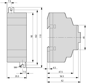
Dimensions (W x H x D)
35.5 x 90 x 58 (2 PE) mm
Weight
0.15 kg
Mounting
Top-hat rail IEC/EN 60715, 35 mm or screw fixing using fixing brackets ZB4-101-GF1 (accessories)
Terminal capacities
Solid
0.2/4 (AWG 22 - 12) mm2
Flexible with ferrule
0.2/2.5 (AWG 22 - 12) mm2
Standard screwdriver
0.8 x 3.5 mm
Max. tightening torque
0.6 Nm
Climatic environmental conditions
Operating ambient temperature
-25 to 55, cold as per IEC 60068-2-1, heat as per IEC 60068-2-2 °C
Condensation
Take appropriate measures to prevent condensation
Storage
- 40 - 70 °C
Relative humidity, non-condensing (IEC/EN 60068-2-30)
5 - 95 %
Air pressure (operation)
795 - 1080 hPa
Ambient conditions, mechanical
Protection type (IEC/EN 60529, EN50178, VBG 4)
IP20
Vibrations (IEC/EN 60068-2-6)Constant amplitude 0.15 mm
10 - 57 Hz
Vibrations (IEC/EN 60068-2-6)Constant acceleration 2 g
57 - 150 Hz
Mechanical shock resistance (IEC/EN 60068-2-27) semi-sinusoidal 15 g/11 ms
18 Impacts
Drop to IEC/EN 60068-2-31 [Drop height]
50 mm
Free fall, packaged (IEC/EN 60068-2-32)
1 m
Mounting position
Vertical or horizontal
Electromagnetic compatibility (EMC)
Overvoltage category/pollution degree
II/2
Electrostatic discharge (IEC/EN 61000-4-2, Level 3, ESD)Air discharge
8 kV
Electrostatic discharge (IEC/EN 61000-4-2, Level 3, ESD)Contact discharge
6 kV
Electromagnetic fields (IEC/EN 61000-4-3, RFI) [V/m]
10
Radio interference suppression
EN 55011 Class B, EN 55022 Class B
Burst Impulse (IEC/EN 61000-4-4, Level 3)Supply cable
2 kV
Burst Impulse (IEC/EN 61000-4-4, Level 3)Signal lines
2 kV
power pulses (surge) (IEC/EN 61000-4-5, level 2)
0.5 (supply cables, symmetrical) kV
Immunity to line-conducted interference to (IEC/EN 61000-4-6)
10 V
Insulation resistance
Clearance in air and creepage distances
EN 50178, UL 508, CSA C22.2, No. 142
Insulation resistance
EN 50178
Power supply
Rated operational voltage [Ue]
24 (-15/+20 %) V
Admissible range
20.4 - 28.8 V DC
Residual ripple
5 %
max. current consumption (at 24 V DC)
Normally 200 mA
Voltage dips
≤ 10 ms
Heat dissipation at 24 V DC
4.8 W
Note on heat dissipation
Current consumption at 24 V DC
Power supply
Residual ripple
< 5 %
Voltage dips
≤ 10 ms
Protection against polarity reversal
AS-I power supply
Yes
LEDs
Supply
Power LED (POW): green
LED display
LED-PROFIBUS-DP (BUS): rot
Network
Connection technique
SUB-D 9 pole, socket
Potential isolation
Between bus and power supply (simple), between bus and power supply and easy base unit (safe isolation)
Function
PROFIBUS-DP slave
Interface
RS485
Bus protocol
PROFIBUS-DP
Baud rates
Automatic search up to 12 MBit⁄s
Bus terminating resistors
Can be connected via plug
Bus addresses
1 - 126, can be addressed via EASY basic unit with display or via EASY-SOFT
ServicesCyclical
All data R1 - R16, S1 - S8
ServicesAcyclical
Read/write, real-time, day, summer/winter time, all the parameters of the EASY function relay
Design verification as per IEC/EN 61439
Technical data for design verification
Static heat dissipation, non-current-dependent [Pvs]
4.8 W
Operating ambient temperature min.
-25 °C
Operating ambient temperature max.
+55 °C
IEC/EN 61439 design verification
10.2 Strength of materials and parts10.2.2 Corrosion resistance
Meets the product standard's requirements.
10.2 Strength of materials and parts10.2.3.1 Verification of thermal stability of enclosures
Meets the product standard's requirements.
10.2 Strength of materials and parts10.2.3.2 Verification of resistance of insulating materials to normal heat
Meets the product standard's requirements.
10.2 Strength of materials and parts10.2.3.3 Verification of resistance of insulating materials to abnormal heat and fire due to internal electric effects
Meets the product standard's requirements.
10.2 Strength of materials and parts10.2.4 Resistance to ultra-violet (UV) radiation
Meets the product standard's requirements.
10.2 Strength of materials and parts10.2.5 Lifting
Does not apply, since the entire switchgear needs to be evaluated.
10.2 Strength of materials and parts10.2.6 Mechanical impact
Does not apply, since the entire switchgear needs to be evaluated.
10.2 Strength of materials and parts10.2.7 Inscriptions
Meets the product standard's requirements.
10.3 Degree of protection of ASSEMBLIES
Meets the product standard's requirements.
10.4 Clearances and creepage distances
Meets the product standard's requirements.
10.5 Protection against electric shock
Does not apply, since the entire switchgear needs to be evaluated.
10.6 Incorporation of switching devices and components
Does not apply, since the entire switchgear needs to be evaluated.
10.7 Internal electrical circuits and connections
Is the panel builder's responsibility.
10.8 Connections for external conductors
Is the panel builder's responsibility.
10.9 Insulation properties10.9.2 Power-frequency electric strength
Is the panel builder's responsibility.
10.9 Insulation properties10.9.3 Impulse withstand voltage
Is the panel builder's responsibility.
10.9 Insulation properties10.9.4 Testing of enclosures made of insulating material
Is the panel builder's responsibility.
10.10 Temperature rise
The panel builder is responsible for the temperature rise calculation. Eaton will provide heat dissipation data for the devices.
10.11 Short-circuit rating
Is the panel builder's responsibility.
10.12 Electromagnetic compatibility
Is the panel builder's responsibility.
10.13 Mechanical function
The device meets the requirements, provided the information in the instruction leaflet (IL) is observed.
Technical data ETIM 7.0
PLC's (EG000024) / Logic module (EC001417)
Electric engineering, automation, process control engineering / Control / Programmable logic control (SPS) / Logic module ([email protected] [AKE539014])
Supply voltage AC 50 Hz
0 - 0 V
Supply voltage AC 60 Hz
0 - 0 V
Supply voltage DC
20.4 - 28.8 V
Voltage type of supply voltage
DC
Switching current
0 A
Number of analogue inputs
0
Number of analogue outputs
0
Number of digital inputs
0
Number of digital outputs
0
With relay output
No
Number of HW-interfaces industrial Ethernet
0
Number of interfaces PROFINET
0
Number of HW-interfaces RS-232
0
Number of HW-interfaces RS-422
0
Number of HW-interfaces RS-485
1
Number of HW-interfaces serial TTY
0
Number of HW-interfaces USB
0
Number of HW-interfaces parallel
0
Number of HW-interfaces Wireless
0
Number of HW-interfaces other
1
With optical interface
No
Supporting protocol for TCP/IP
No
Supporting protocol for PROFIBUS
Yes
Supporting protocol for CAN
No
Supporting protocol for INTERBUS
No
Supporting protocol for ASI
No
Supporting protocol for KNX
No
Supporting protocol for MODBUS
No
Supporting protocol for Data-Highway
No
Supporting protocol for DeviceNet
No
Supporting protocol for SUCONET
No
Supporting protocol for LON
No
Supporting protocol for PROFINET IO
No
Supporting protocol for PROFINET CBA
No
Supporting protocol for SERCOS
No
Supporting protocol for Foundation Fieldbus
No
Supporting protocol for EtherNet/IP
No
Supporting protocol for AS-Interface Safety at Work
No
Supporting protocol for DeviceNet Safety
No
Supporting protocol for INTERBUS-Safety
No
Supporting protocol for PROFIsafe
No
Supporting protocol for SafetyBUS p
No
Supporting protocol for other bus systems
Yes
Radio standard Bluetooth
No
Radio standard WLAN 802.11
No
Radio standard GPRS
No
Radio standard GSM
No
Radio standard UMTS
No
IO link master
No
Redundancy
No
With display
No
Degree of protection (IP)
IP20
Basic device
No
Expandable
Yes
Expansion device
Yes
With timer
No
Rail mounting possible
Yes
Wall mounting/direct mounting
Yes
Front build in possible
No
Rack-assembly possible
No
Suitable for safety functions
No
Category according to EN 954-1
None
SIL according to IEC 61508
None
Performance level acc. EN ISO 13849-1
None
Appendant operation agent (Ex ia)
No
Appendant operation agent (Ex ib)
No
Explosion safety category for gas
None
Explosion safety category for dust
None
Width
36 mm
Height
90 mm
Depth
60 mm
Approvals
Product Standards
IEC/EN see Technical Data; UL 508; CSA C22.2 No. 142-M1987; CSA C22.2 No. 213-M1987; CE marking
UL File No.
E135462
UL Category Control No.
NRAQ, NRAQ7
CSA File No.
012528
CSA Class No.
2252-01 + 2258-02
North America Certification
UL listed, CSA certified
Degree of Protection
IEC: IP20, UL/CSA Type: -
Dimensions
Datasheet - PDF
▲| Title: | Size: | Type: |
|---|---|---|
| PDF EATON SAFETY LOGIC EN.pdf | 2 Mbytes |

|
| EASY204-DP 0004520914 212316 EN_212316.pdf | 200 Kbytes |
|
Reviews (0) ▲
No customer reviews for the moment.
Add Review
hide form
| Rating: |
|
| Name: | |
| Email: | |
| Subject: | |
| Text: | |
| Do you recommend this product to buy? | |
|
|
|
| Add review | |
All ratings we receive from the items we offer are real and verified. A small gesture, but a lot of value. That's why we thank you for that minute you invest in leaving us your opinion and qualification about the products, because it helps us to continue improving and to offer you a service of even higher quality.