Keine Artikel
Produkt wurde in den Korb gelegt
 Vergrößern
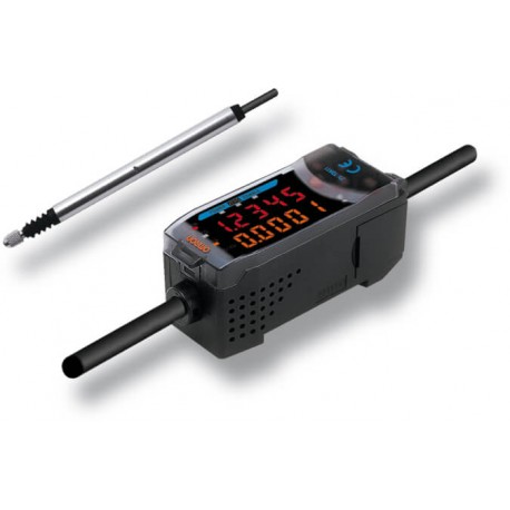
ZS-XPM2 177223 OMRON Adapter für schalttafeleinbau expansion
ZS-XPM2
177223
ZSXPM2
OMRON
Adapter für schalttafeleinbau expansion
Erweiterungsrahmen-Montageadapter
Erweiterte Sensoren > Zubehör Erweiterte Sensoren
* Neues Produkt in der Originalverpackung mit allen Garantien und Zertifizierungen von OMRON
Mehr Infos
▲- Modulares Plattformkonzept für unterschiedliche Erfassungstechnologien
- Luftgefederte Ausführungen für automatische Prüfanwendungen
- Mehrpunktmessungen mit bis zu acht Sensoren
- Druckkraftalarm verhindert Fehlfunktionen
- Robuste Kugellagerstruktur garantiert eine lange Lebensdauer
Spezifikationen & Bestellinfo
Ordering information
Sensors
Sensor heads
Note: The resolution refers to the minimum value that can be read when a ZX-TDA_1 amplifier unit is connected.
Amplifier units
Accessories (order separately)
Calculating unit
ZX-series communications interface unit
SmartMonitor sensor setup tool for Personal Computer connection
ZX-SW11EV31 |
Cables with connectors on both ends (for extension)*
*Robot cable models are also available. The model numbers are ZX-XC_R.
Preamplifier mounting brackets
Actuators
Measuring ordinary flat surfaces (standard |  | ||||
 | |||||
 | |||||
 | |||||
 | |||||
Mounting D5SN-TN1/-TF1 or commercially |  |
Note: Replacement possible
 Conversion adapter required
Specifications
Amplifier units
Possible average count settings3 | ||
Linear output4 | Current output: 4 to 20 mA/F.S., max. load resistance: 300 Ω Voltage output: ±4 V (±5 V, 1 to 5 V5), output impedance: 100 Ω | |
NPN open-collector outputs, 30 VDC, 30 mA max. | PNP open-collector outputs, 30 VDC, 30 mA max. | |
Zero reset input, timing input, reset input, judgement output hold input | ON: Supply voltage short-circuited or supply voltage of 1.5 V or less | |
| ||
Judgement indicators: High (orange), pass (green), low (yellow), 7-segment main digital display (red), 7-segment sub-digital | ||
140 mA max. (with sensor connected), for 24-VDC power supply voltage: 140 mA max. (with sensor connected) | ||
Operating and storage: 0 to 50°C (with no icing or condensation) | ||
Case: PBT (polybutylene terephthalate), cover: Polycarbonate | ||
Sensor heads
Resolution7 | ||||
Linearity8 | ||||
Operating force9 | ||||
Operating: 0 to 50°C, storage:-15 to 60°C (with no icing or condensation) | ||||
Operating and storage: 35% to 85% (with no icing or condensation) | ||||
Temperature characteristic10 | ||||
Instruction manual, preamplifier mounting brackets (ZX-XBT1) | ||||
1.When using the ZX-TDA11/41 with the SmartMonitor, either the ZX-SFW11EV3 or the
ZX-SW11EV3 SmartMonitor must be used. Earlier versions cannot be used.
3.The response speed of the linear output is calculated as the measurement period x (average count setting + 1).
The response speed of the judgement outputs is calculated as the measurement period x (average count setting + 1).
4.The output can be switched between a current output and voltage output using a switch on the bottom of the amplifier unit.
7.The resolution is given as the minimum value that can be read when a ZX-TDA_1 amplifier unit is connected. This value is taken 15 minutes after turning ON the power with the average number of operations set to 256.
9.These figures are representative values that apply for the measurement mid-point, and are for when the provided actuator is used, with the actuator moving downwards. If the actuator moves horizontally or upwards, the operating force will be reduced. Also, if an actuator other than the standard one is used, the operating force will vary with the weight of the actuator itself.
Datasheet - PDF
▲| Titel: | Größe: | Typ: |
|---|---|---|
| ZS-XPM2 ZSXPM2 177223 DE_ZX-TDS01T.pdf | 884 Kbytes |
 |
| ZS-XPM2 ZSXPM2 177223 zs_l_brochure_de.pdf | 2 Mbytes |
 |
Bewertungen (0) ▲
Es gibt keine Produktbewertungenvor.
| Wertung: |


|
| Name: | |
| E-Mail : | |
| Betreff: | |
| Text: | |
| Haben Sie dieses Produkt empfehlen zu kaufen? | |
|
|
|
| Bewertung abgeben | |
Alle Bewertungen wir von den Einzelteilen erhalten wir anbieten, sind real und verifiziert. Eine kleine Geste, aber sehr wertvoll. Also danke für die Minute, die Sie in, dass Sie uns Ihre Meinung und Bewertung von Produkten ausgeben, weil es mir hilft, weiter zu verbessern und noch mehr Servicequalität zu bieten.


